Casing up
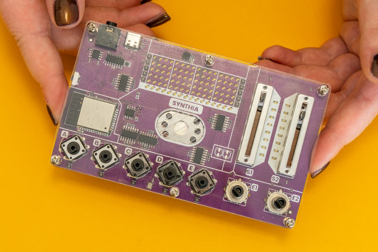
If you came here, your device successfully passed the hardware test!
That means you are on track to becoming a professional maker!
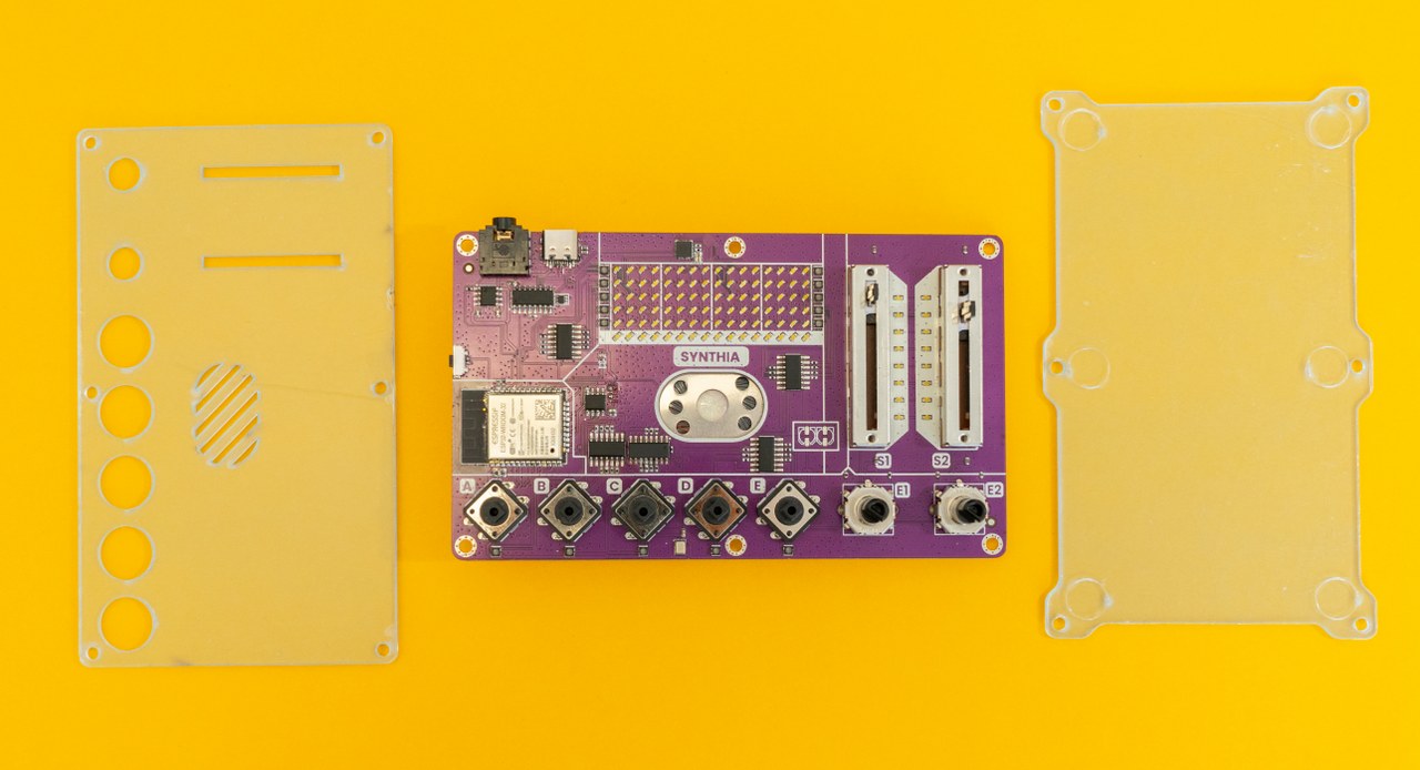
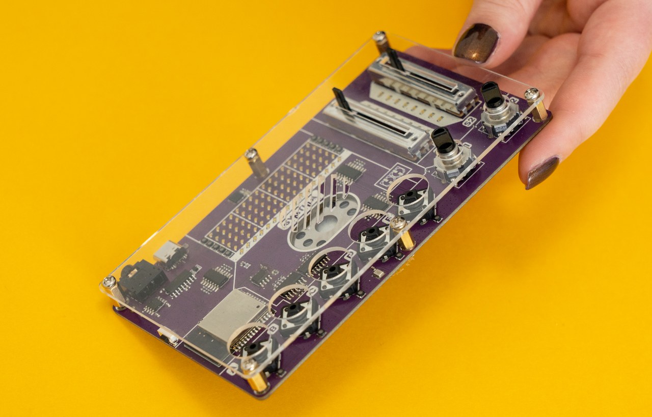
Now, we need to use the two acrylic casings to protect the PCB and make your device look more professional.
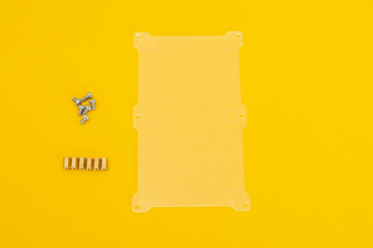
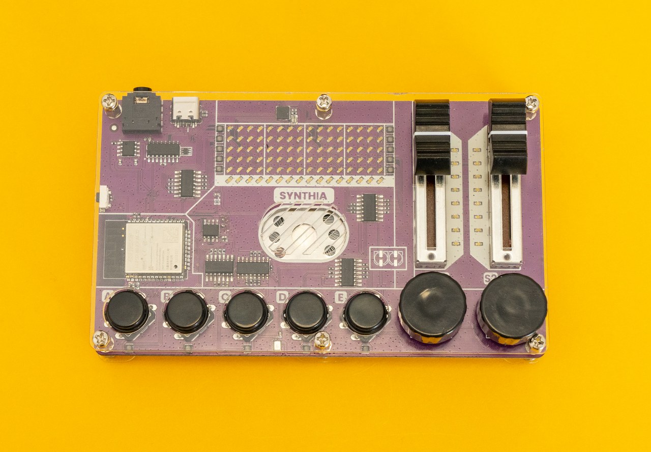
For this part, these parts will be the main ones.
Each acrylic casing part has a protective layer on both sides that needs to be peeled off. They are not yet fully transparent, but they should be once you finish this step!
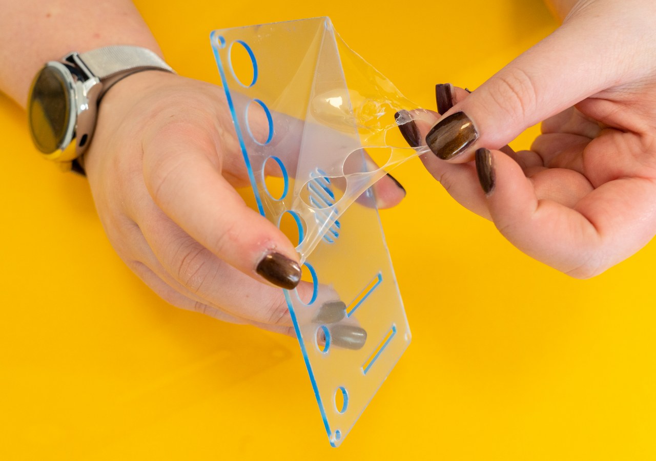
Remember to peel the protective layer from both sides of the casings!
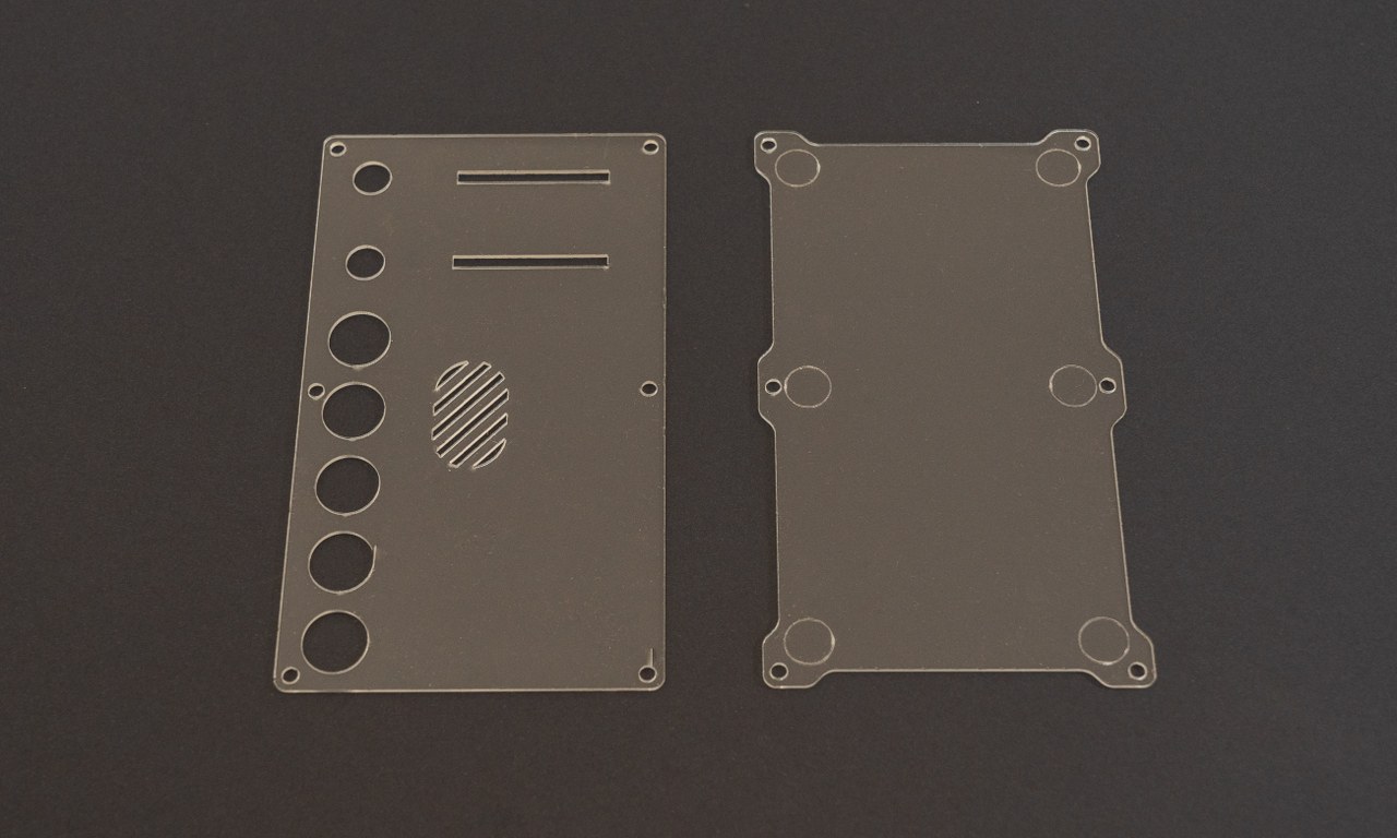
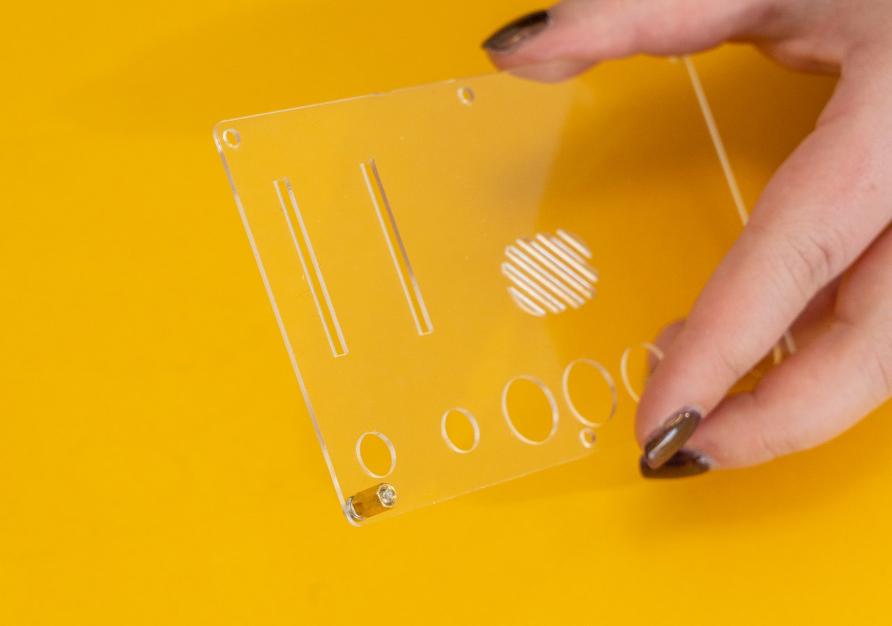
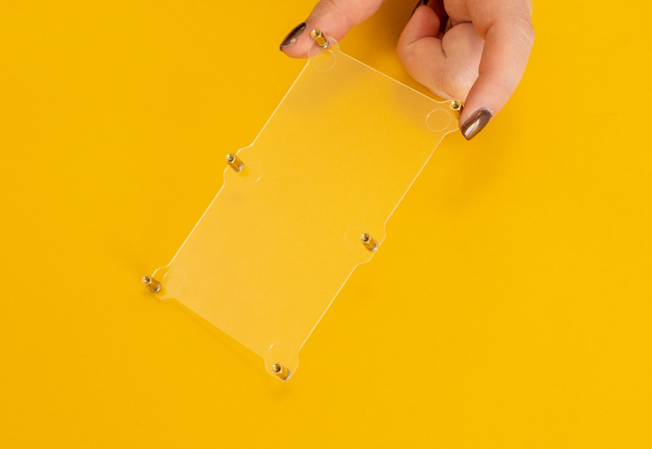
After you peeled off everything, this is what the casings should look like:
We chose to put the upper casing first (that is the one with all the holes on it)!
For that, you'll need the bigger screws and the gold standoffs.
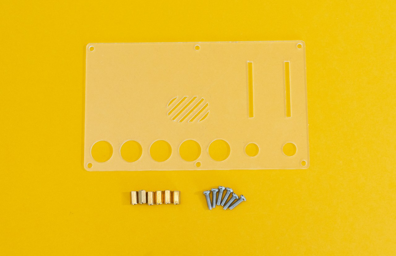
As you can see, there are six screws and six standoffs.
You'll place them in the six little holes at the edge of the acrylic casing and PCB.
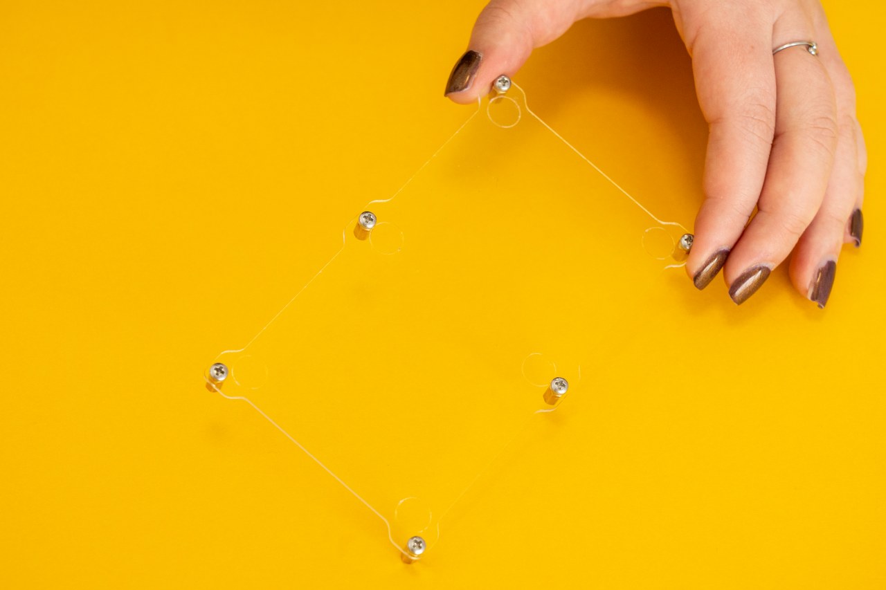
We recommend you put one screw and one standoff, ensure that everything is secured, and then go to the next screw and standoff.
The important thing is to put the screw from the outside of the acrylic casing and the standoff from the inner side.
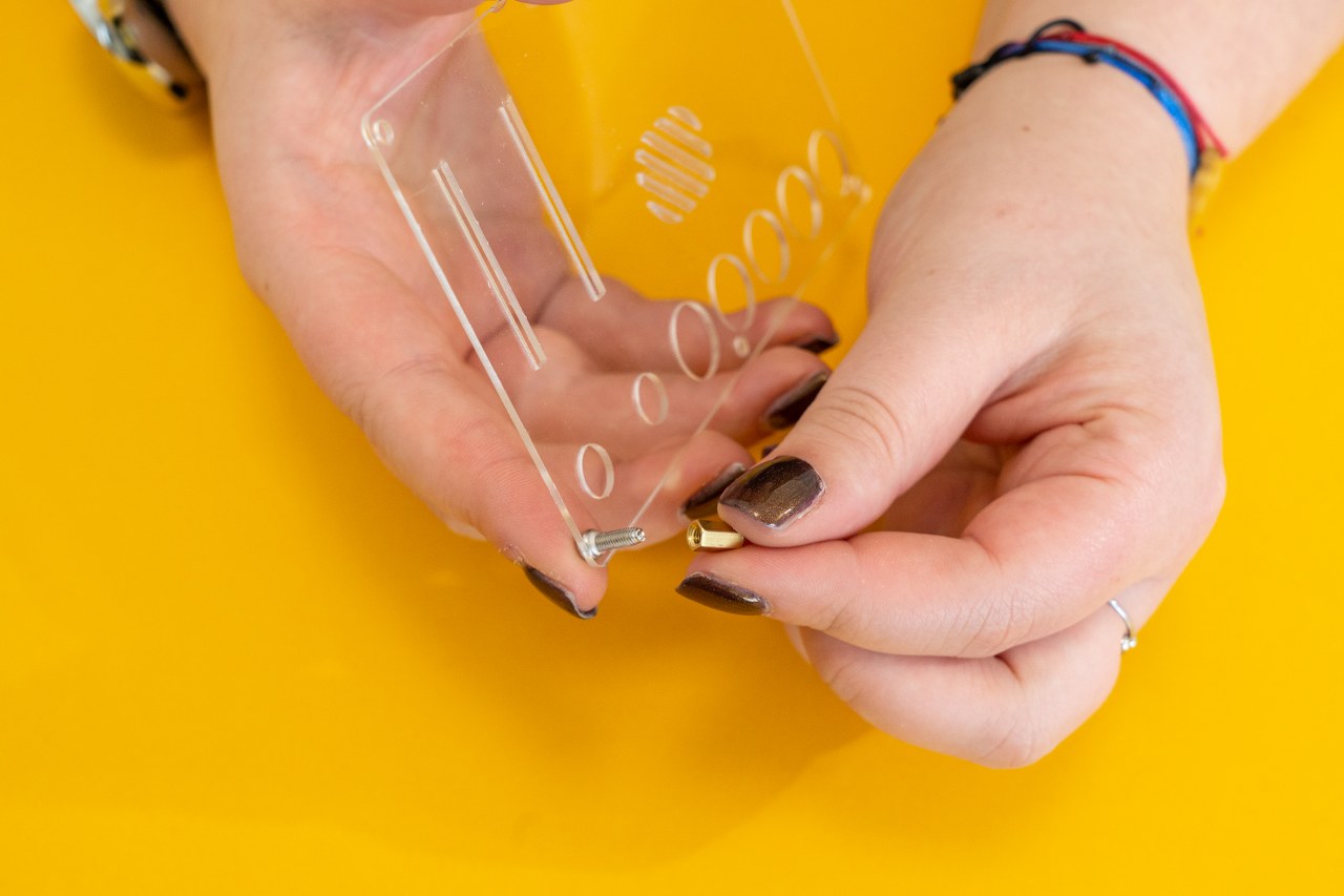
You'll have to fasten it with your fingers. No tools are needed yet!
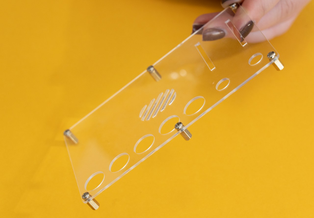
Now, do the same thing for all six of them!
This is what you should have at the end!
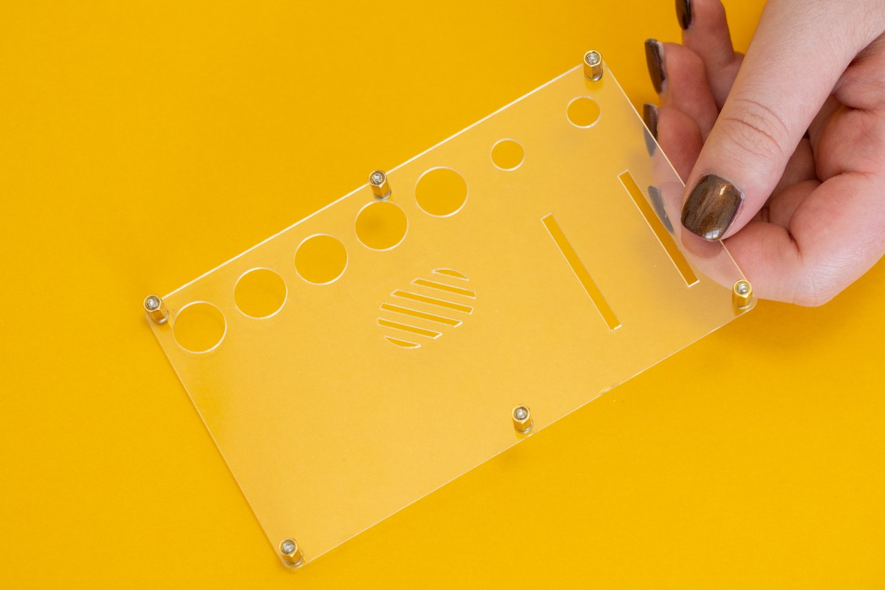
Put this casing on the front side of the PCB.
Off to use the other acrylic casing!
This is what you'll be working with: the acrylic casing you have left, six standoffs,
and six smaller screws.
The process is the same as for the front casing.
Take one screw and one standoff, and fasten it. The screws have to go to the outside of the casing and the standoffs to the inner side.
You'll recognize the sides by the six circles! On the outside, you'll be able to touch the edges of the circle!

Repeat this for all of the six screws and standoffs:

Now, take the PCB and this acrylic casing, and let's connect everything!
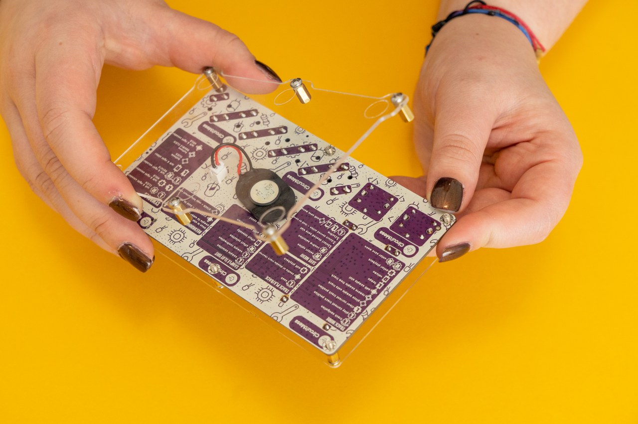
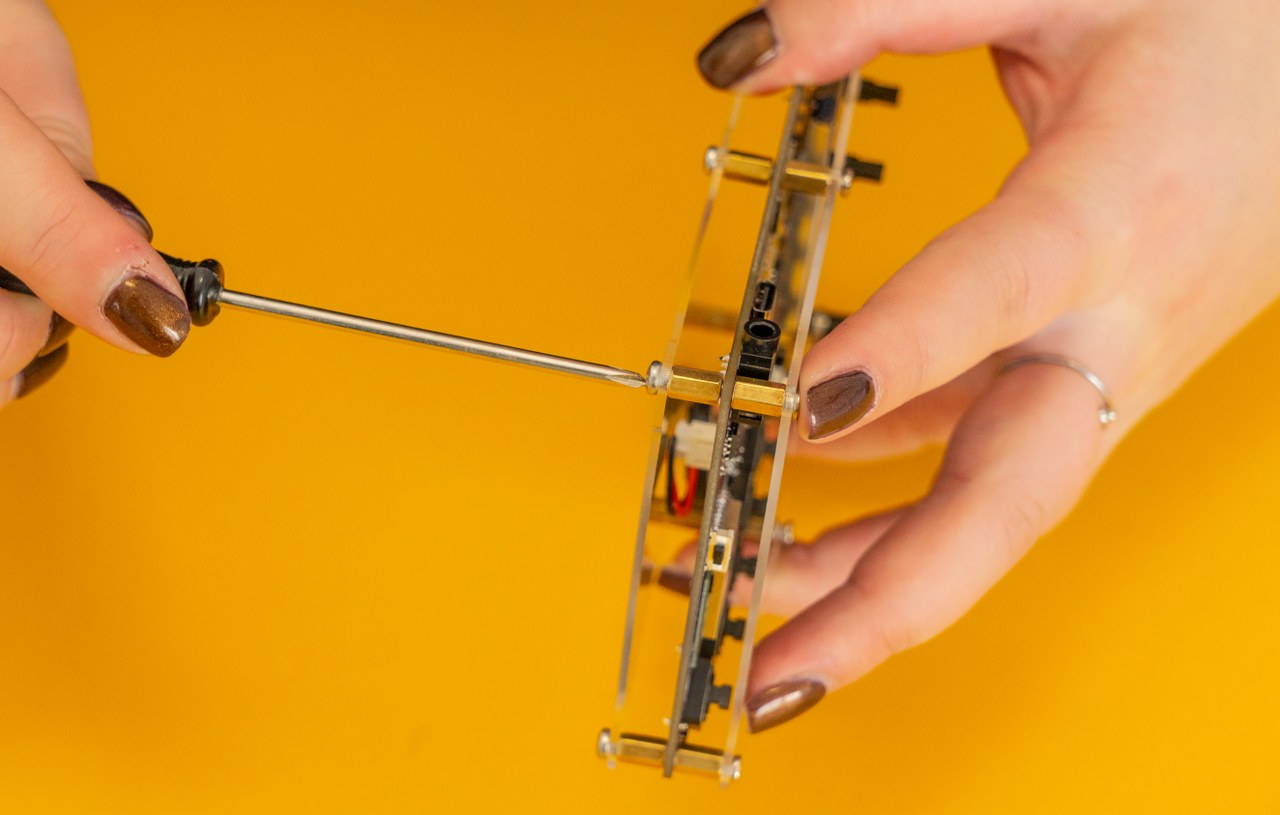
Now, take the screwdriver and fasten the screws!
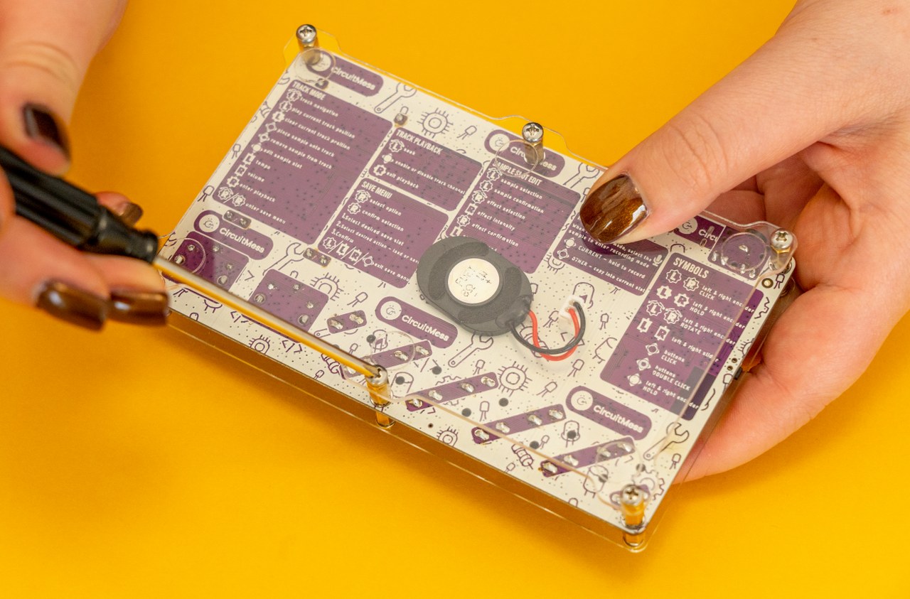
Beware not to screw it too hard because that could lead to the breaking of the casing!
Everything is connected now! Amazing!
Now is the time to put buttons and encoder caps to make your experience smoother.
We'll start with the encoder caps. Those are the two biggest caps from the bag.
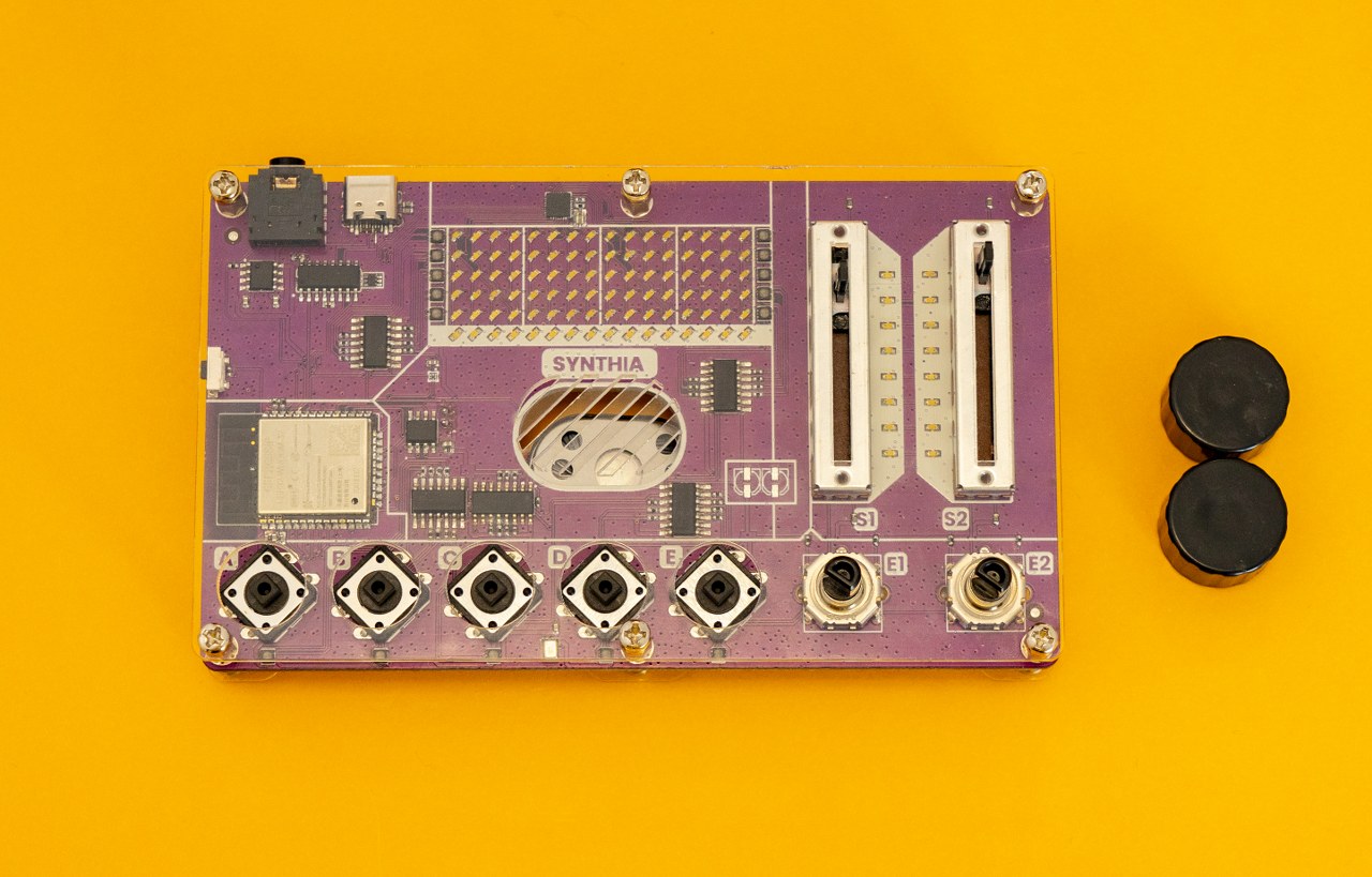
Put it right here:
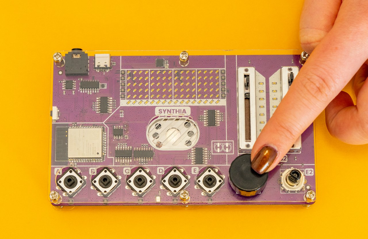
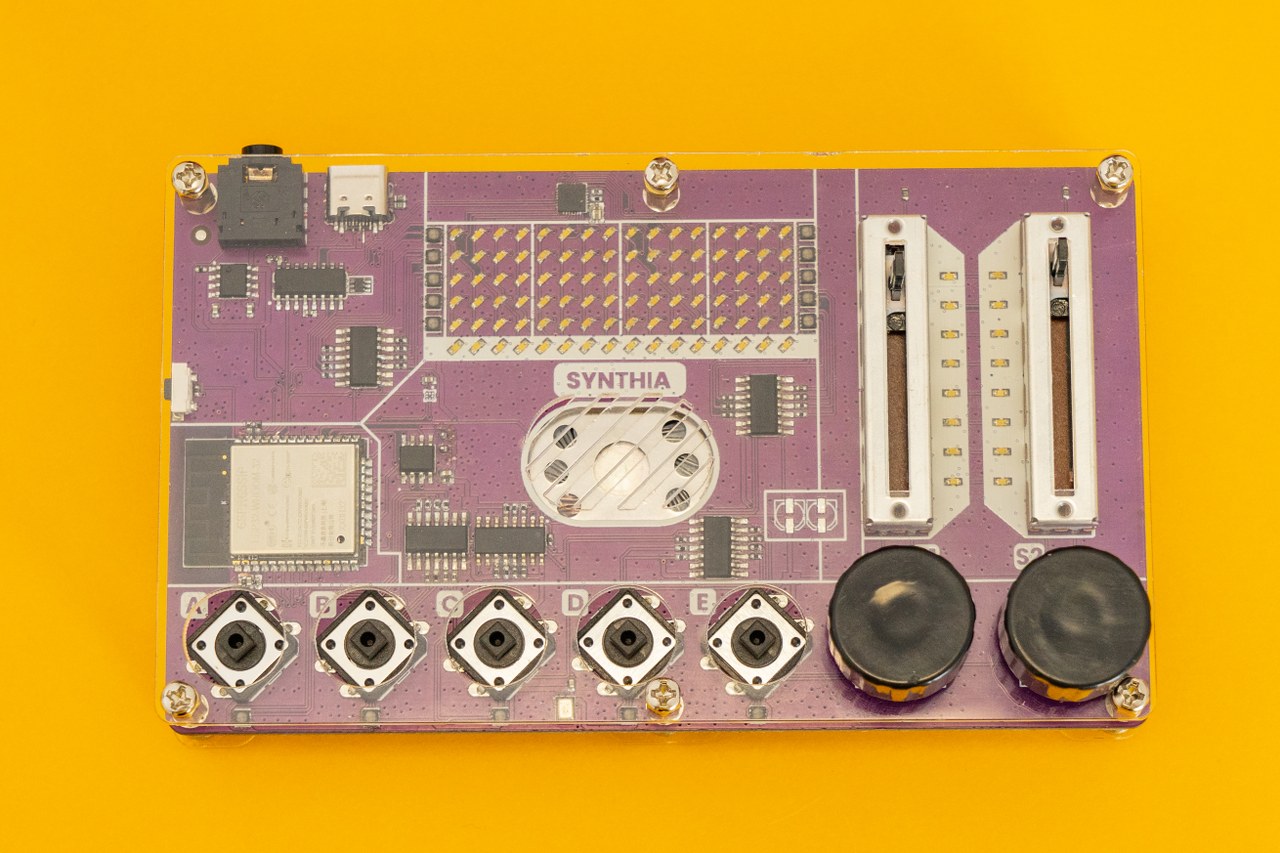
Make sure to push the cap on the encoder until it clicks.
After putting them on the encoders, try to use them a bit to see if everything is
put on correctly.
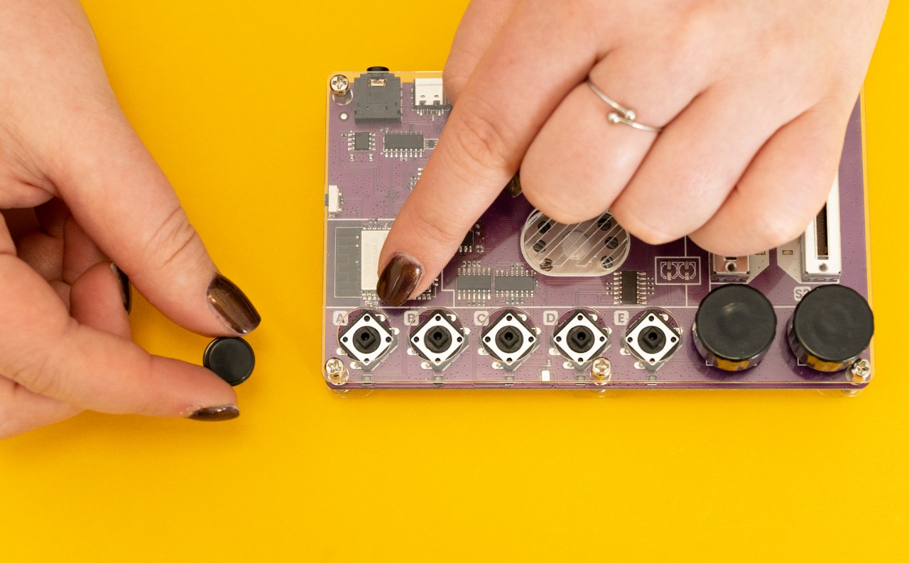
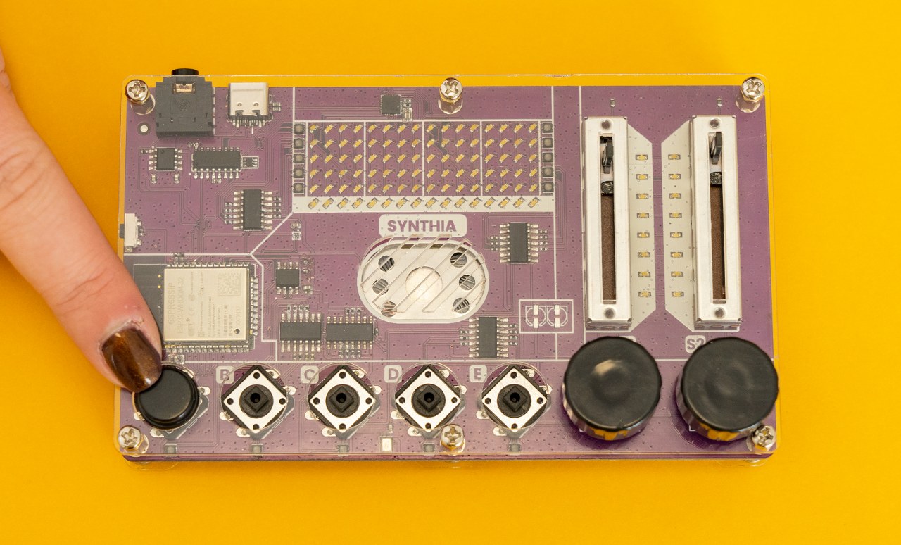
The next thing we'll need is the pushbutton caps.
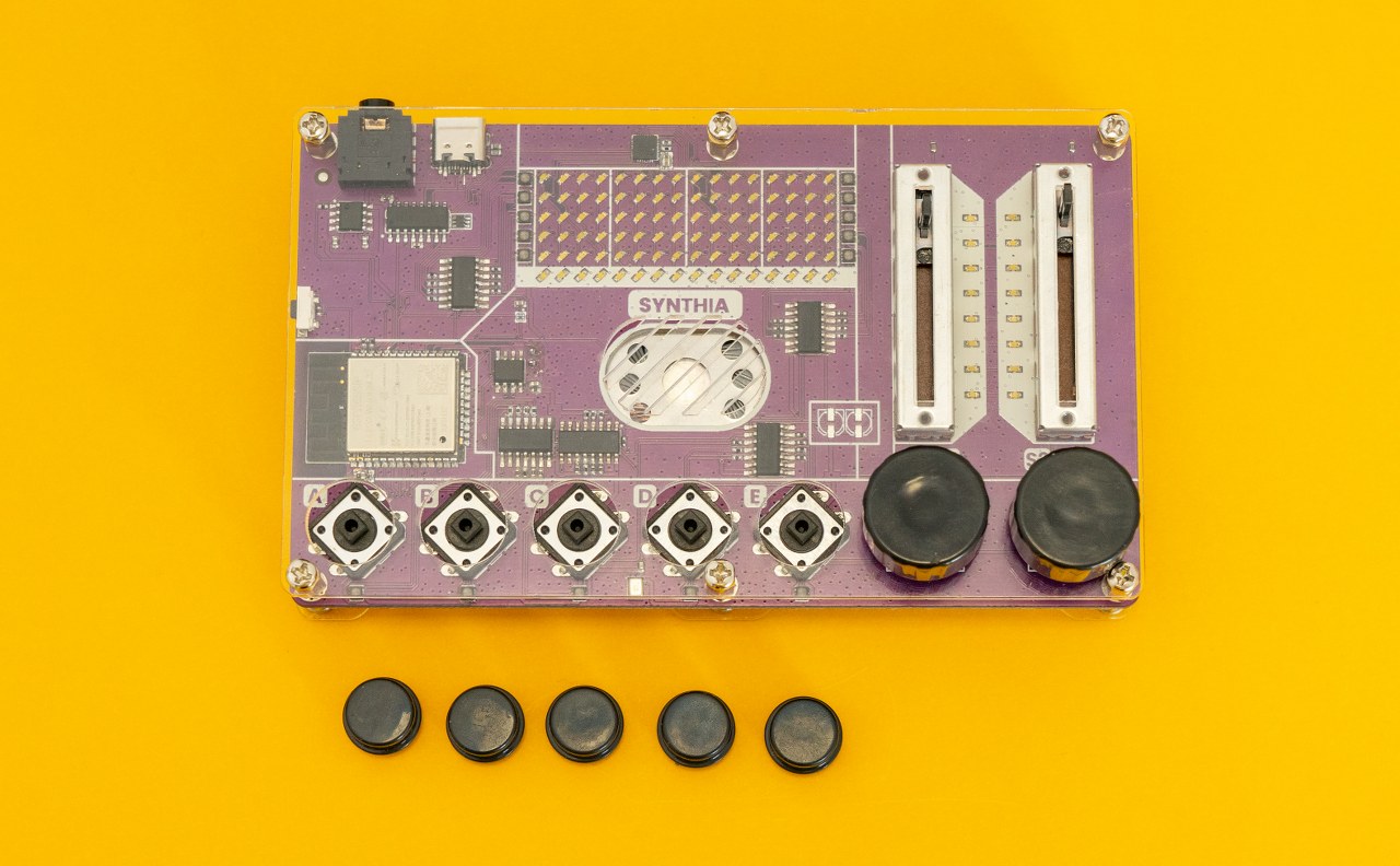
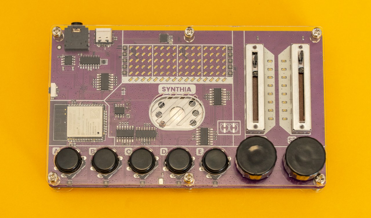
As for the encoder caps, push them on the button until they click.
Make sure everything works smoothly before going to the next step.
The next thing to do is put caps on sliders.
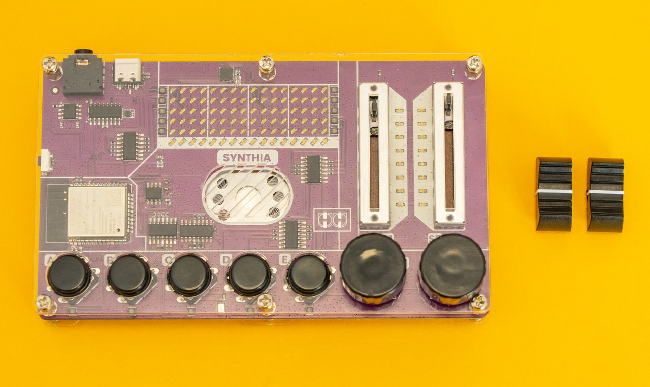
After putting them on, slide them a bit to make sure everything works as it
should!
Great job!
We came to the end of the assembly.
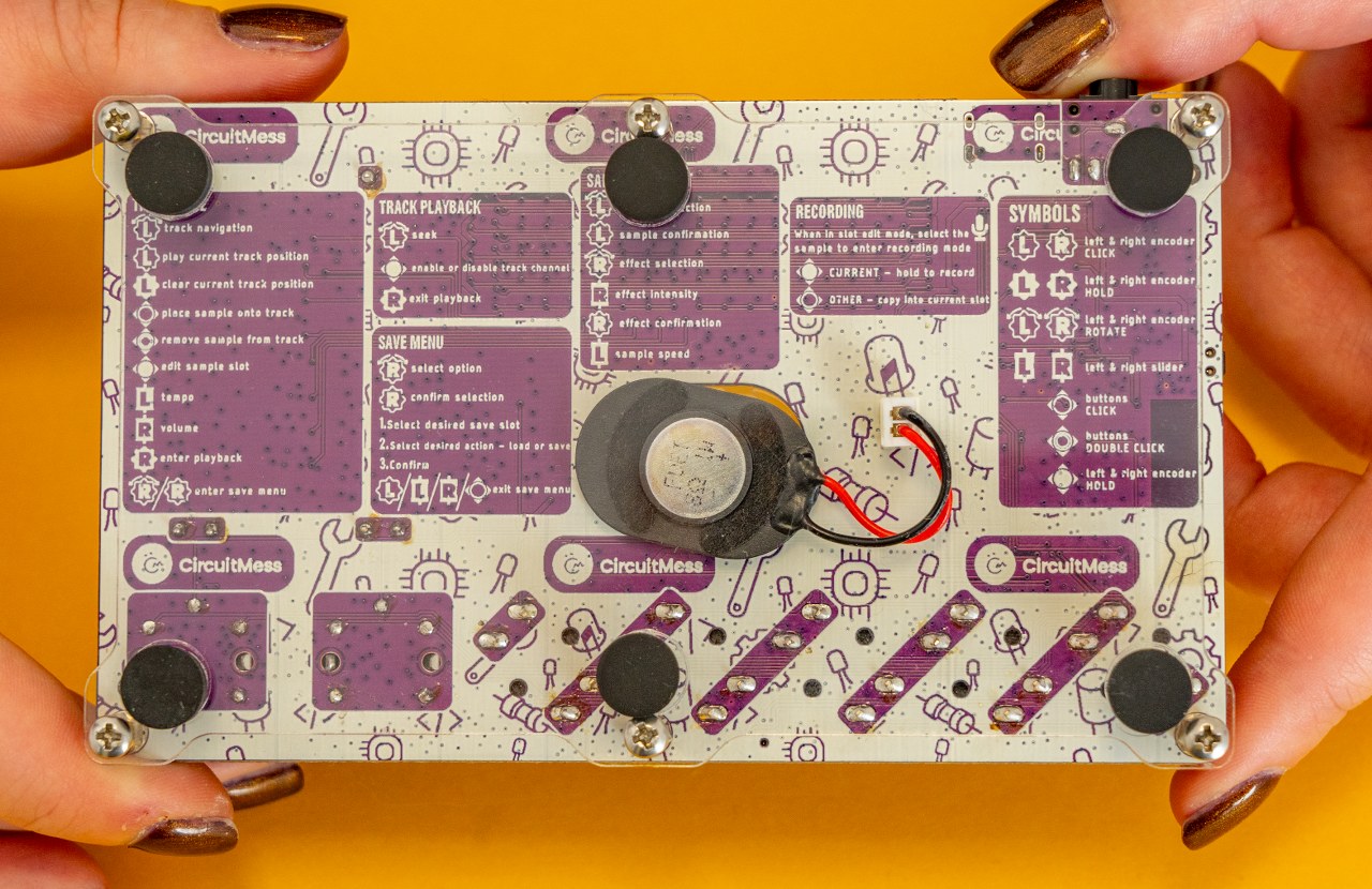
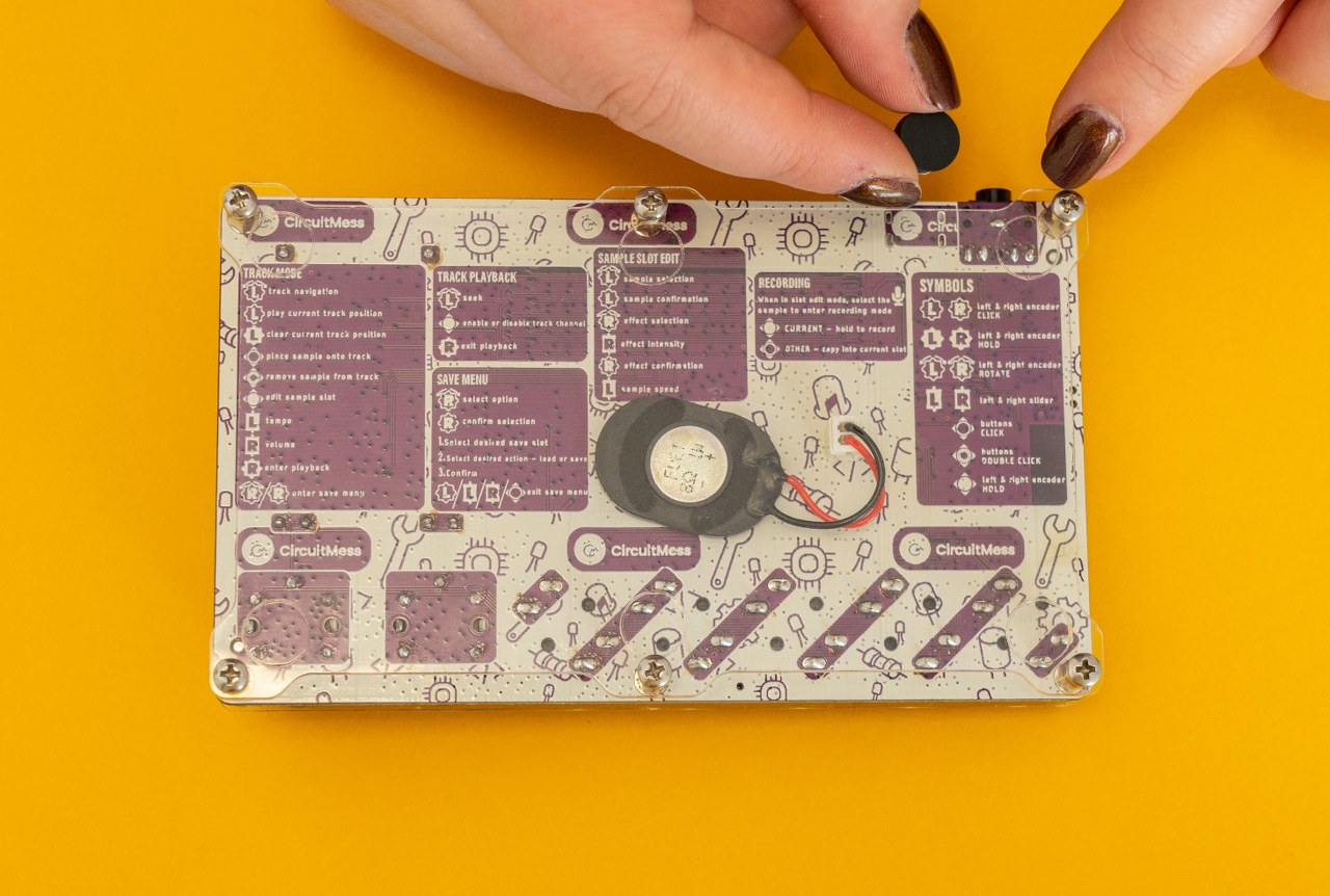
The only thing left to do is to put adhesive rubber feet at the bottom of the device to secure it.
These are the parts you'll need:
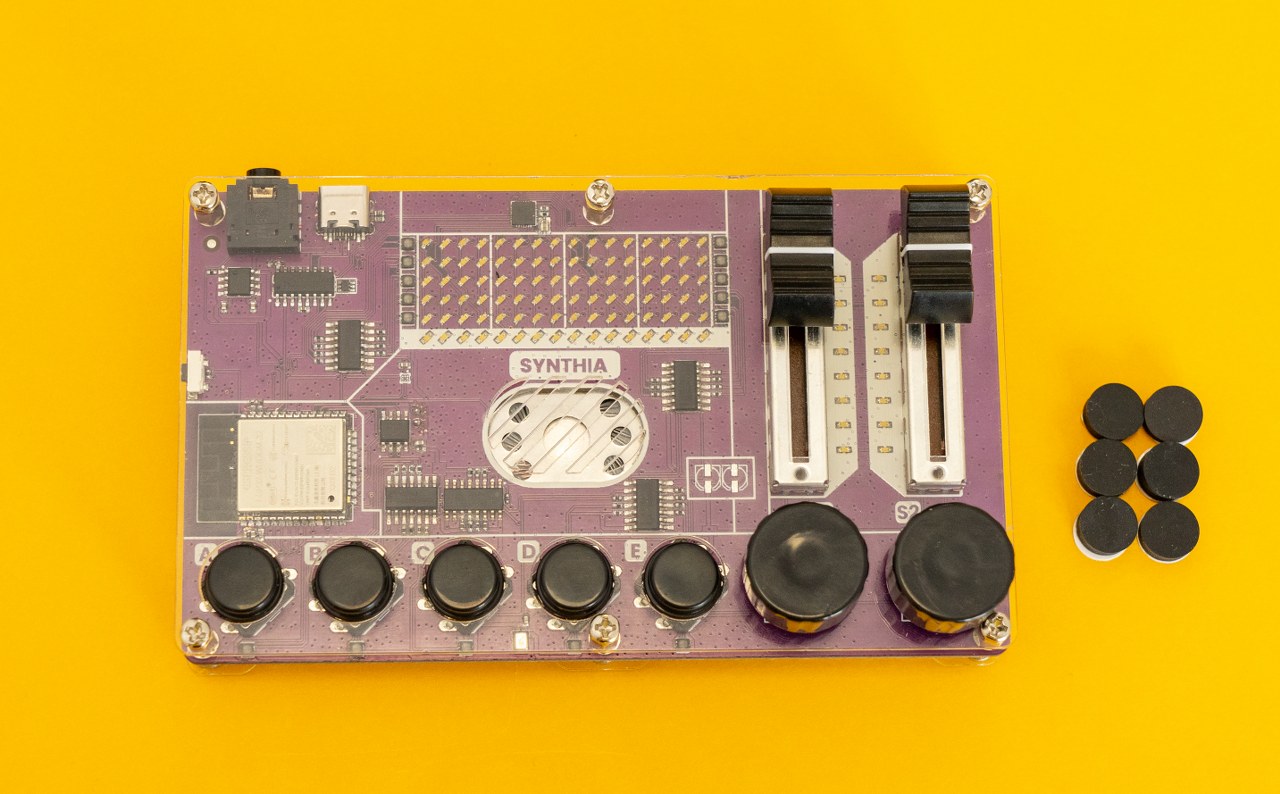
As you can see, there are white stickers under each of the rubber feet. You'll have to remove the sticker before putting them on the casing.
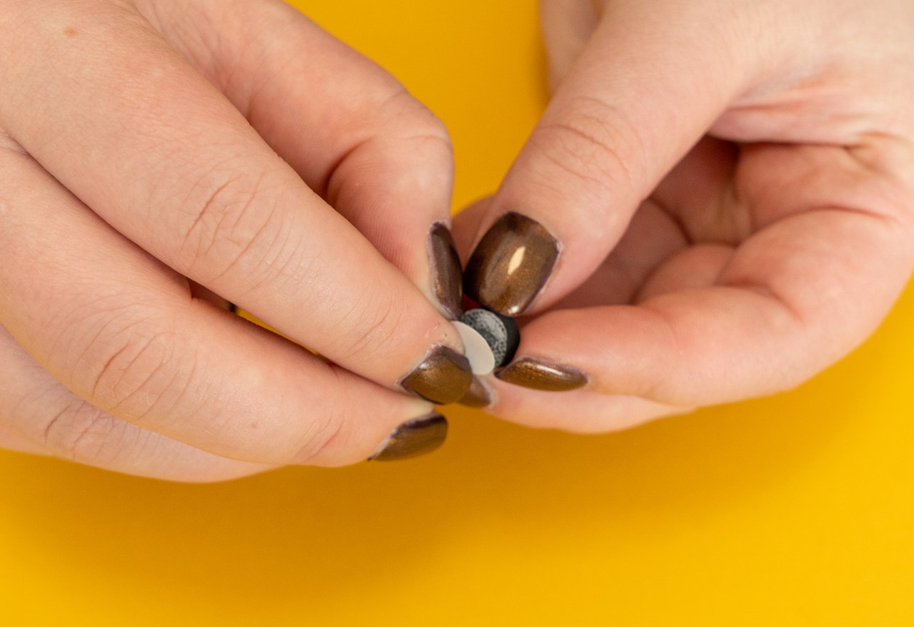
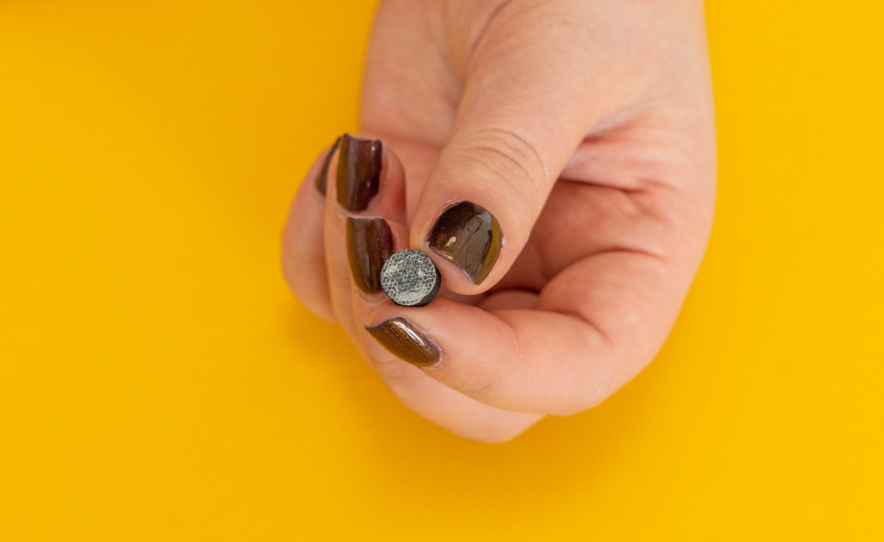
Stick the sticky side of the rubber feet to the bottom of the device.
This is what Synthia should look like after sticking the rubber feet!