

Chapter One - Soldering the components
Now that you know how to solder, let's put it to the test. Ready?
Part one - Soldering the components
This is a crucial step that has to be done before you do any soldering at all!
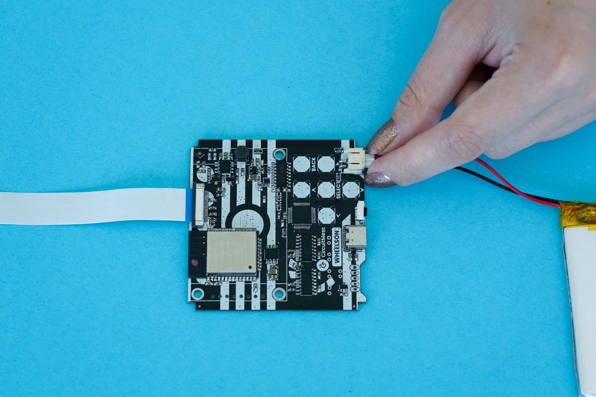
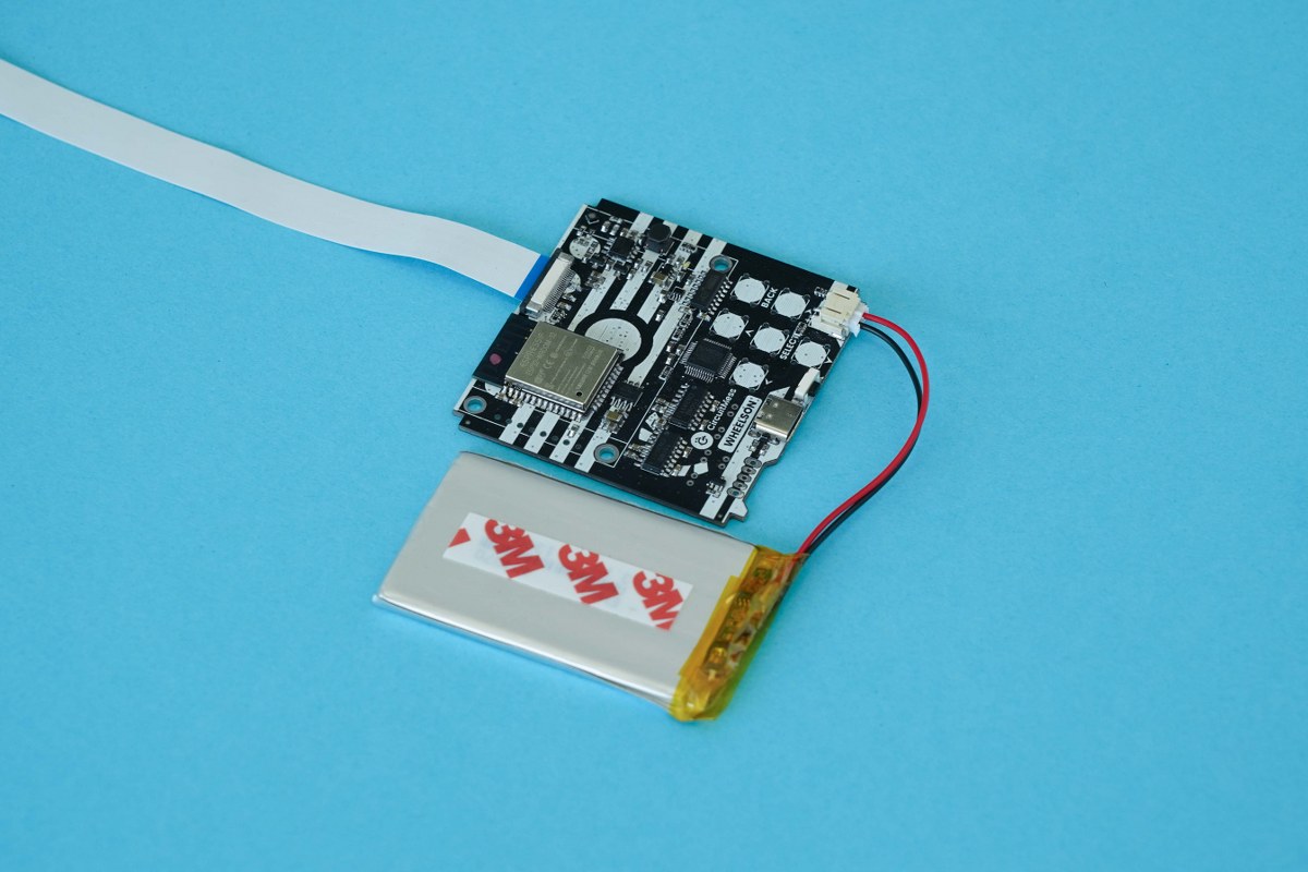
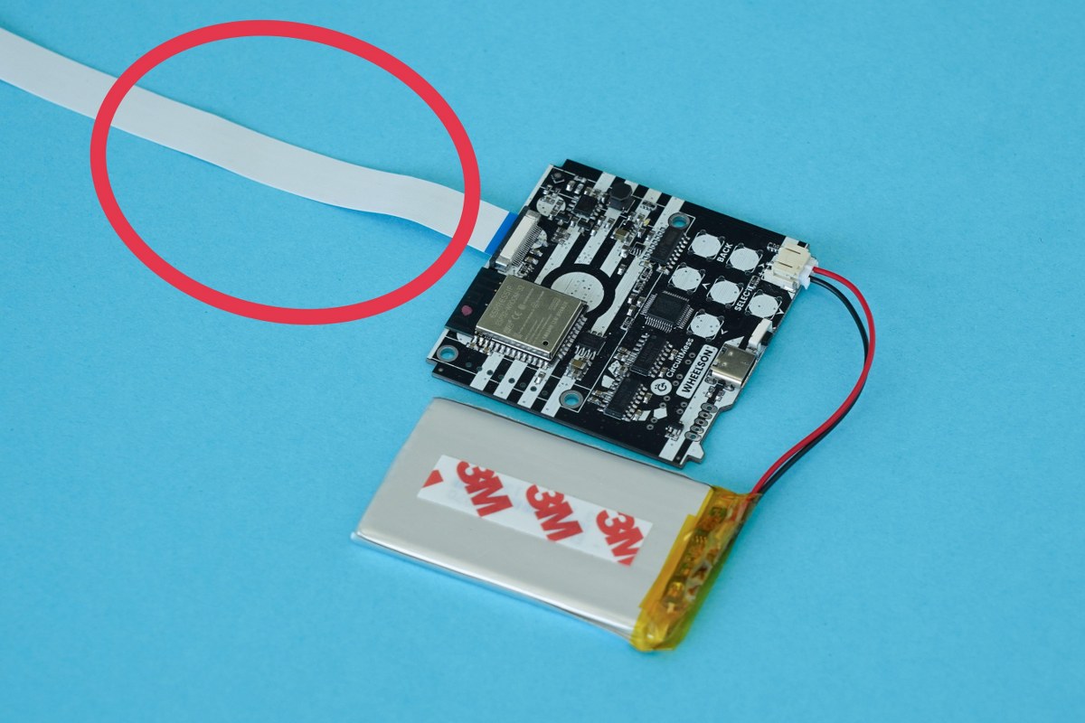
Unplug the battery from the board
Do not skip this step, you must unplug the battery before beginning the soldering process.
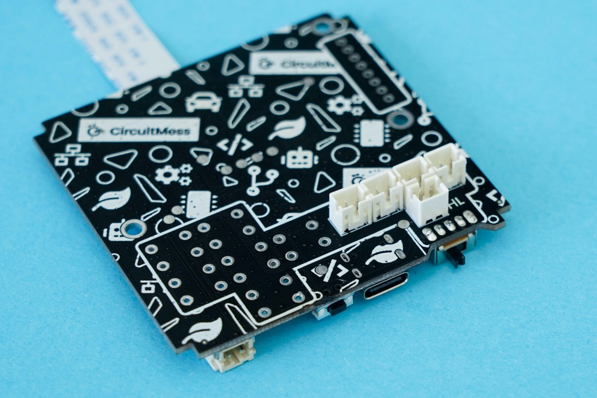
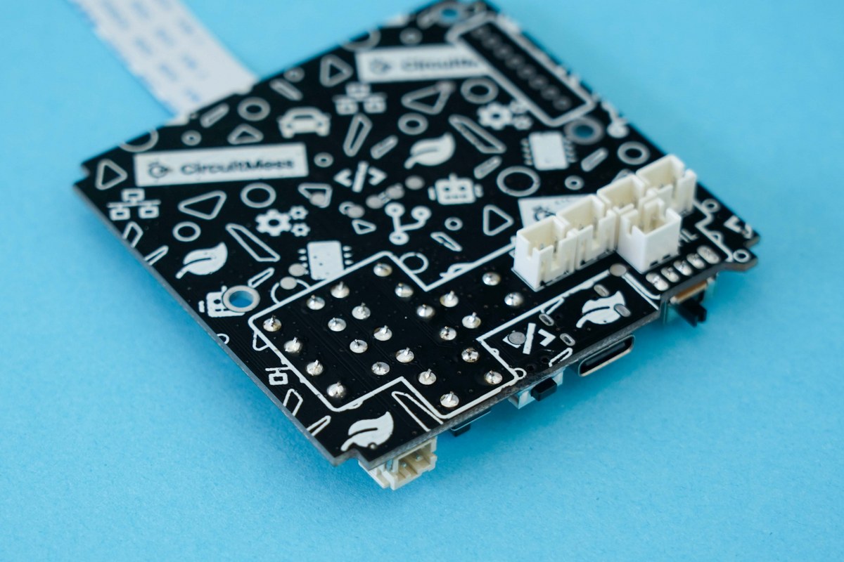
Flip over the board while being careful not to make sudden movements with the camera cable hanging from the board, and position the 5 JST connectors on the board like so.
Insert the JST connectors all the way in
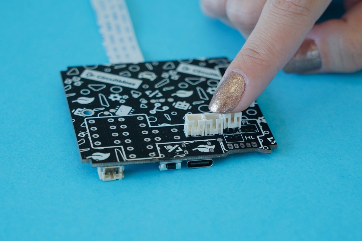
You'll see that one side of the JST connector has holes on it. Make sure that those holes are facing away from the camera and the camera connector on the other side of the board! Place four JST connectors next to each other on the board in that way.
The fifth and last JST connector should be placed in the opposite direction with the holes facing towards the camera, camera connector, and the other connectors.
Here's a photo of how they should be placed:
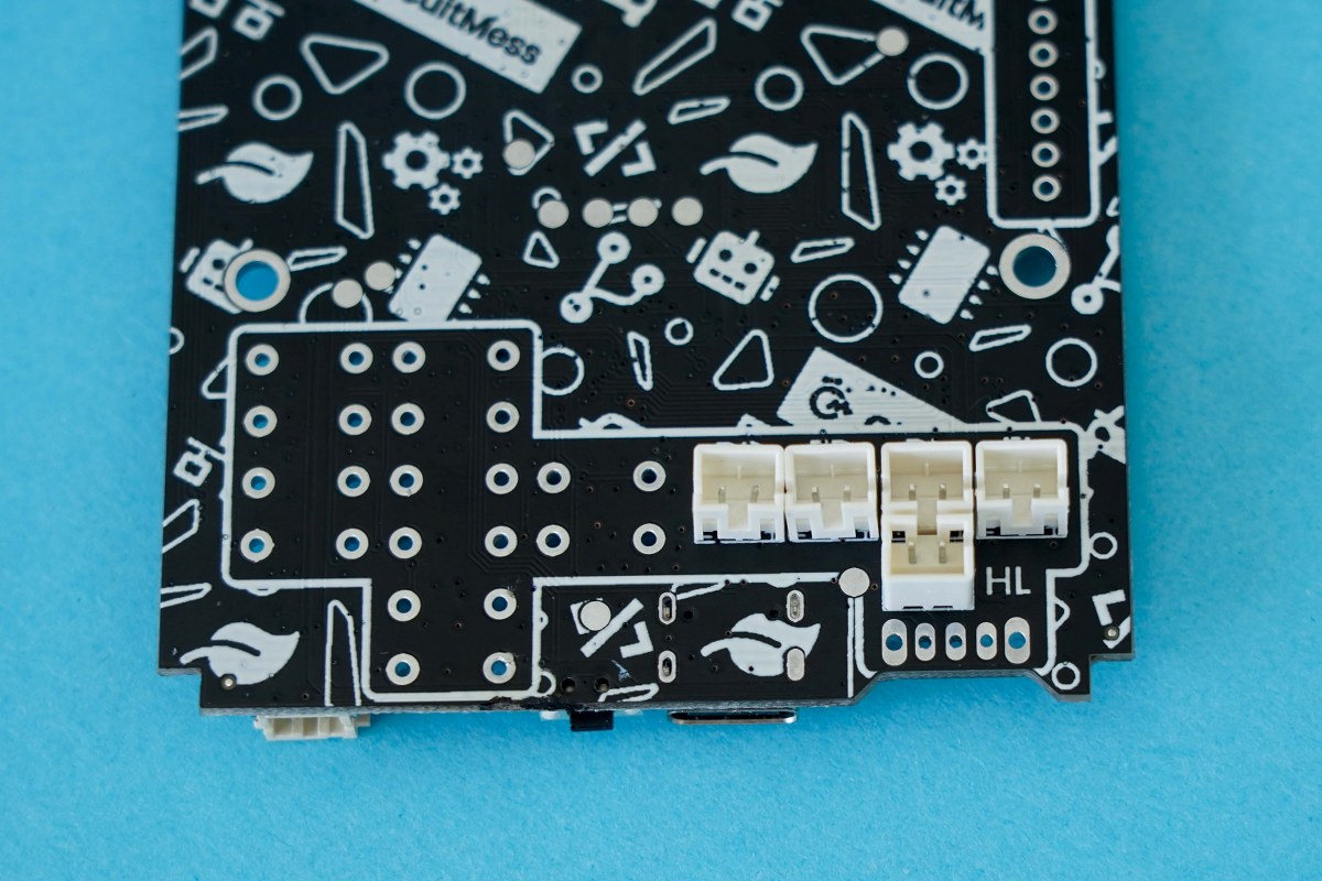
Your JST connectors should be positioned on the board like this
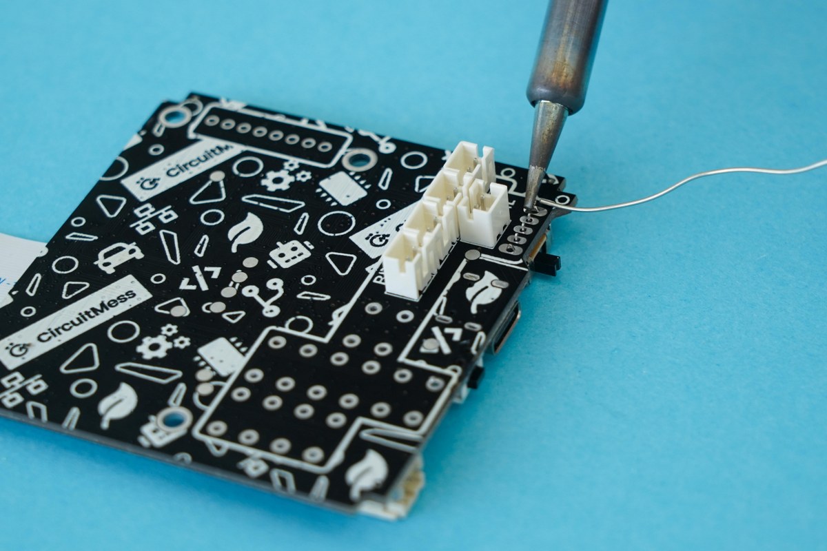
You'll see where the connector pins are sticking out of the board next to the CircuitMess Wheelson logo. There are ten soldering connections in total you have to make here.
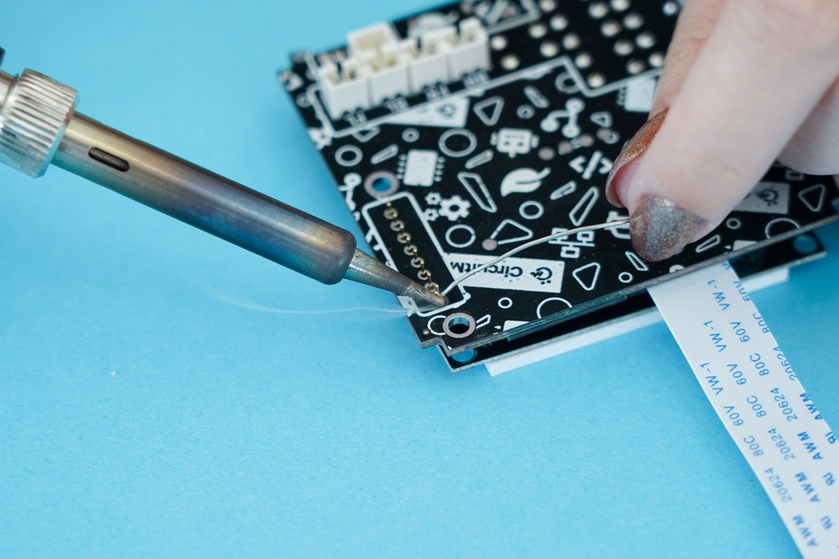
Turn over the board and get ready to solder the first pin
First, carefully place the soldering iron on the first pin so that it’s touching both the pin and the little plated area around the hole that the pin is going through.
Leave it like that for about 5 to 10 seconds, so it heats up, and then apply the tip of the solder to pin/pad. The solder should easily melt and spread evenly around the joint.
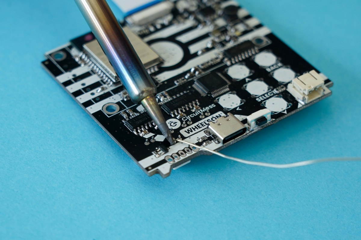
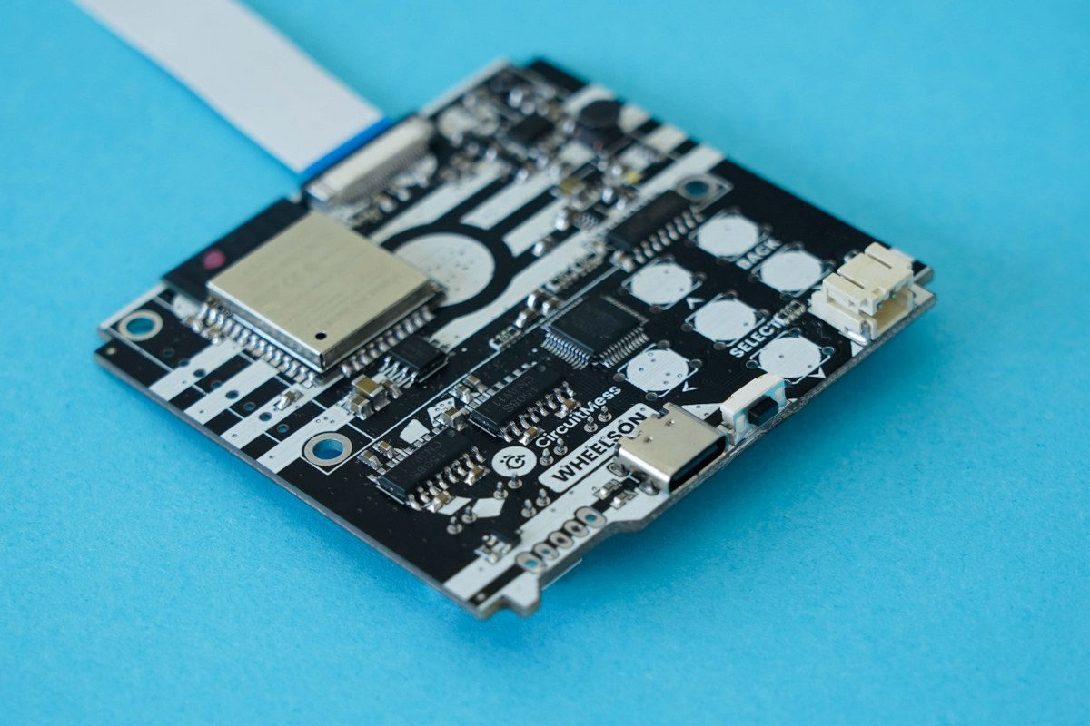
Make the first connection
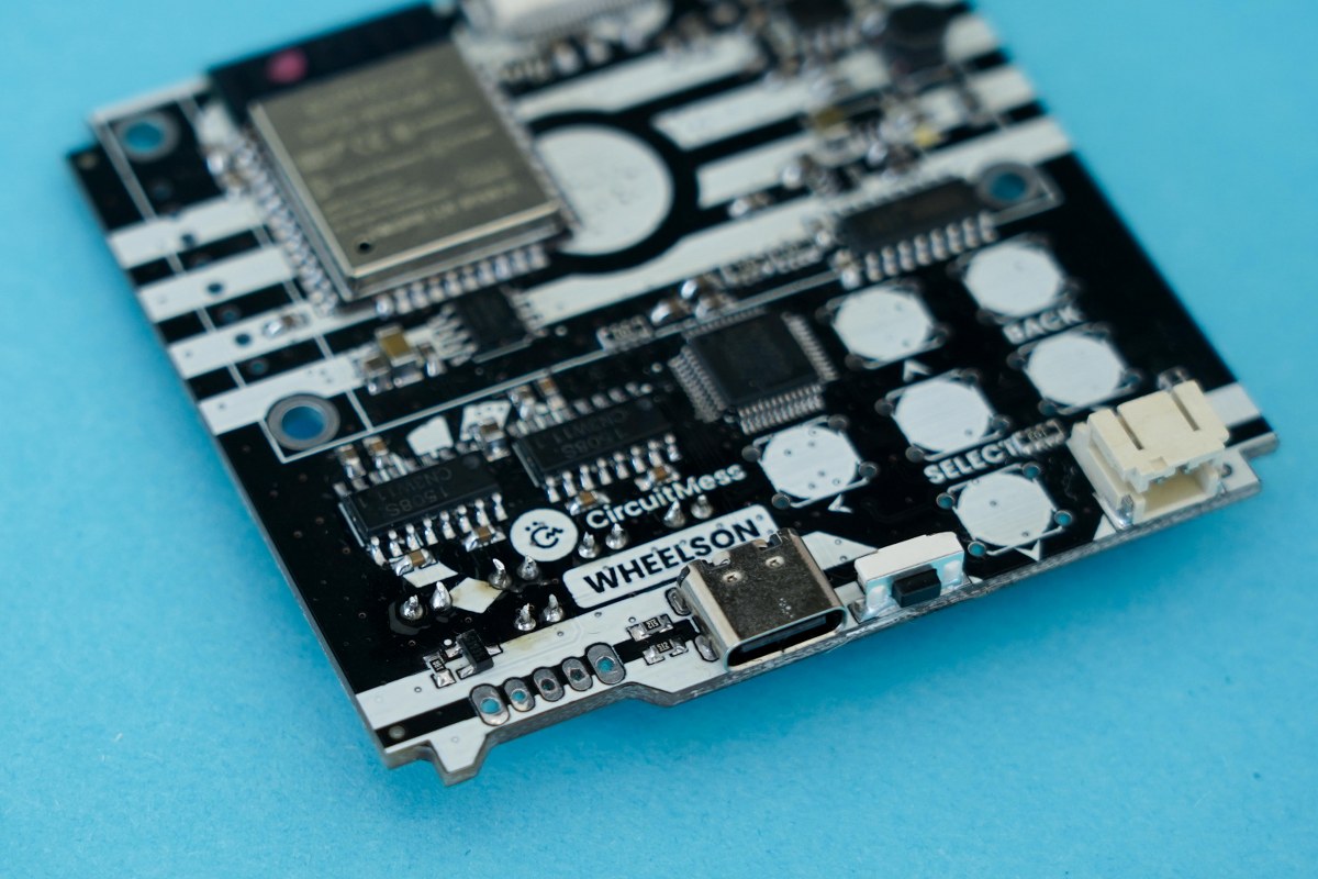
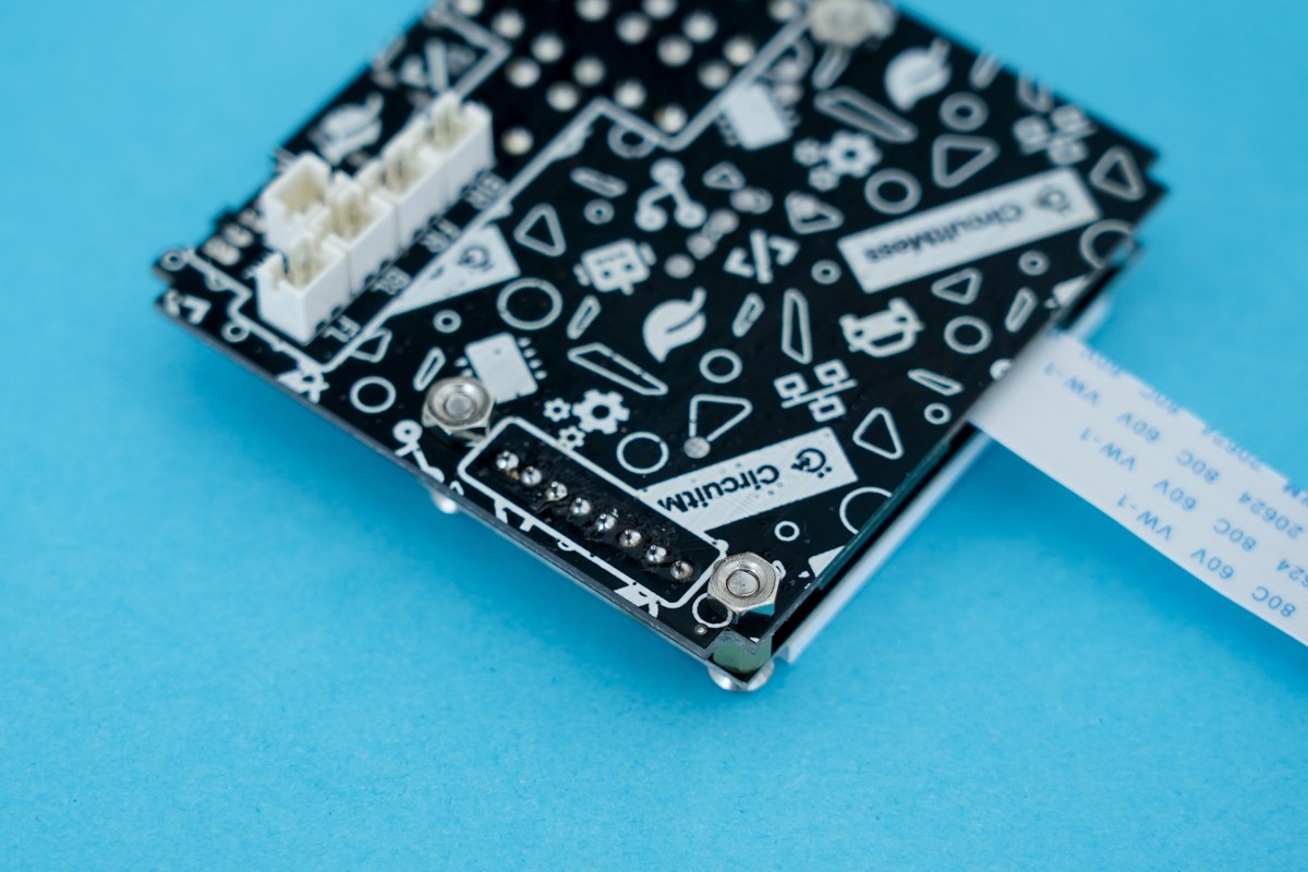
This is how your soldering connections should look

Great job! You soldered the first components to the board.
Part two - Soldering the switch button
- Main circuit board
- Switch button
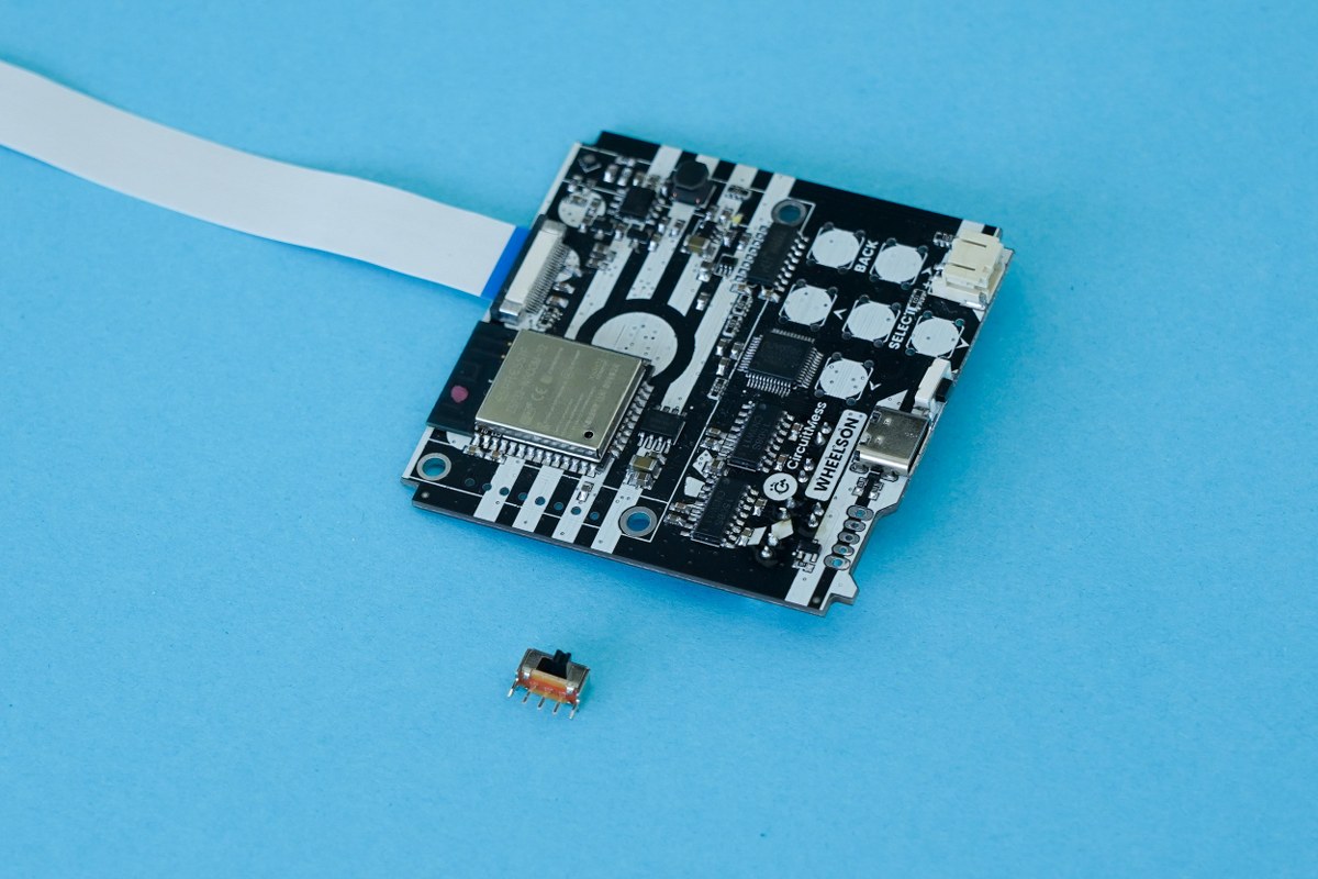
Circuit board and the switch button
A quick side note: you can get one of the two versions of the switch button.One version has the switch on the top, and the other has the switch on its side.
Regardless of which version of the switch button you get, they will both work completely fine.
(Watch out not to burn yourself! When you are doing this, make sure you do not touch the pin that you soldered/are heating up as this will be hot!)
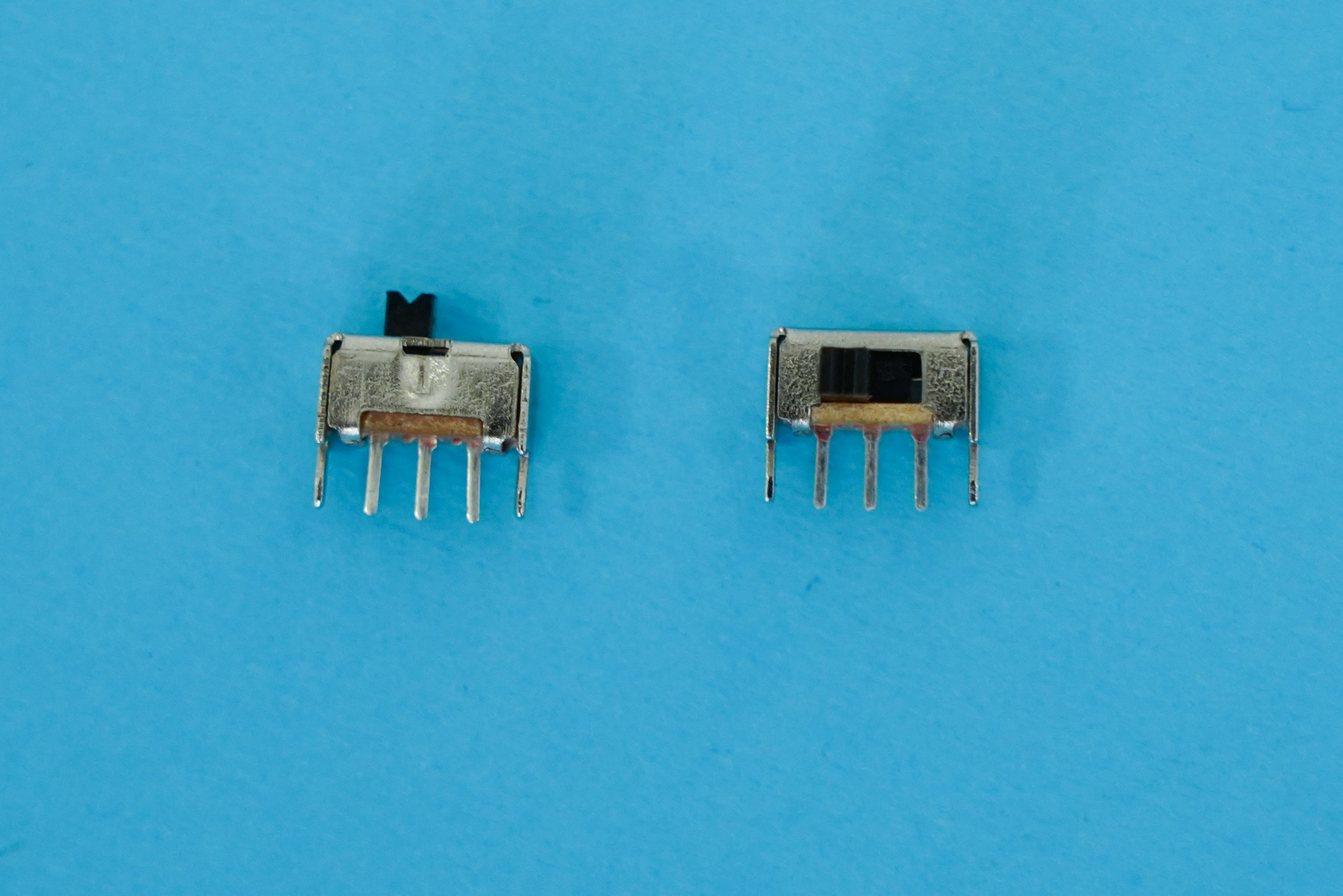
The two versions of the switch button
Now we need to find its place on the board.
First, find the CircuitMess Wheelson logo on the board. On the left of the logo, near the bottom of the board, there should be five holes. This is where you should place your switch. Make sure to push it all the way in.
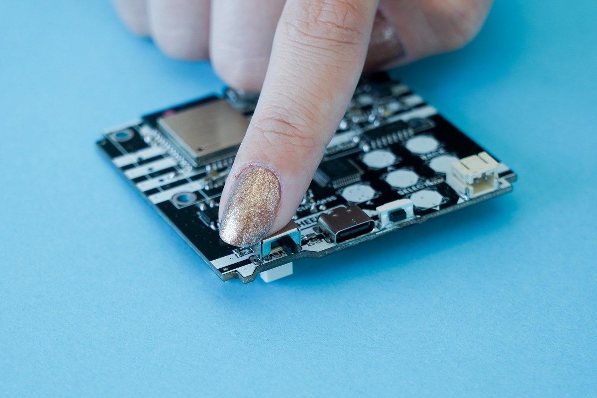
Push the switch button into the holes on the board
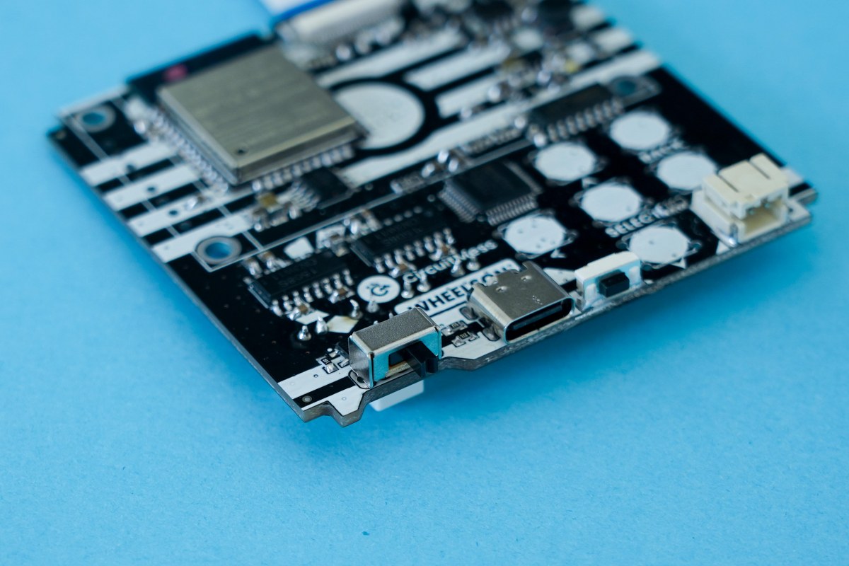
This is how the switch button should look after it's inserted
Turn the board over and start by soldering the first pin. Repeat the procedure for the rest of the pins.
Soldering the switch button to the board
This is what the soldering connections should look like
Part three - Soldering the buttons
- The main board
- Six Pushbuttons
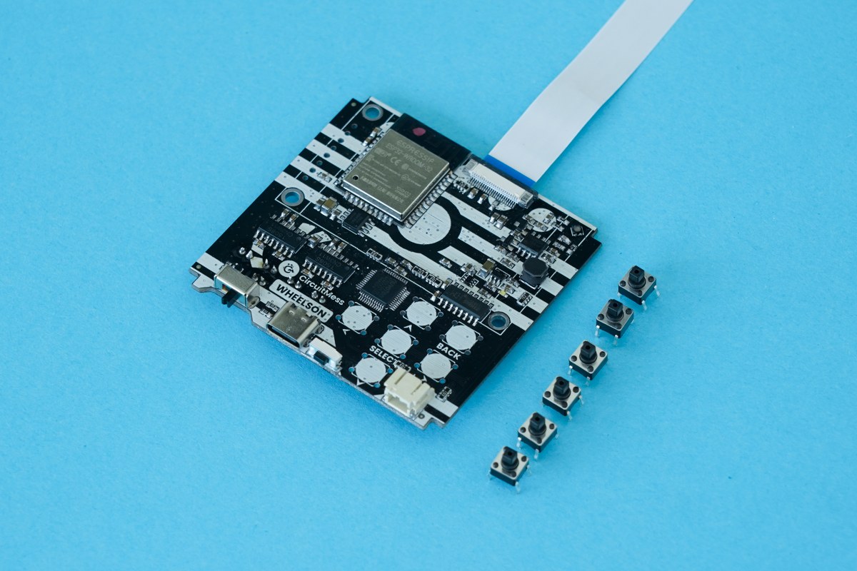
The circuit board and six pushbuttons
Heads up - the pushbutton pins are shaped like a rectangle, so make sure to fit them accordingly. Also, ensure that the pins go all the way through the board - you might have to push a bit harder in order for them to go all the way through the board and sit flat.
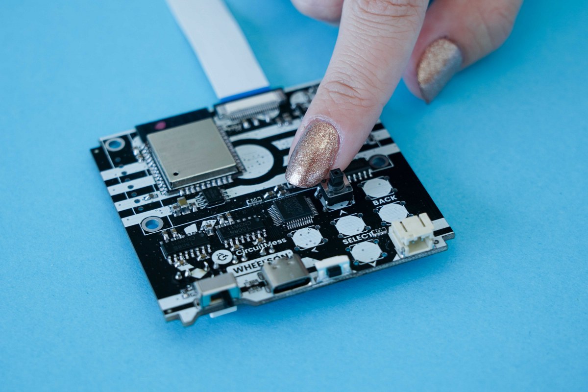
Insert the pushbuttons
Insert all six pushbuttons
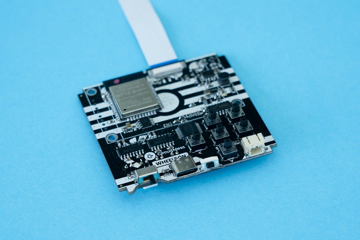
There are quite a few soldering connections to be made here, so take your time.
Make sure that all the buttons sit flat, you may have to press the buttons a couple of times to make sure they are fitted securely in place.
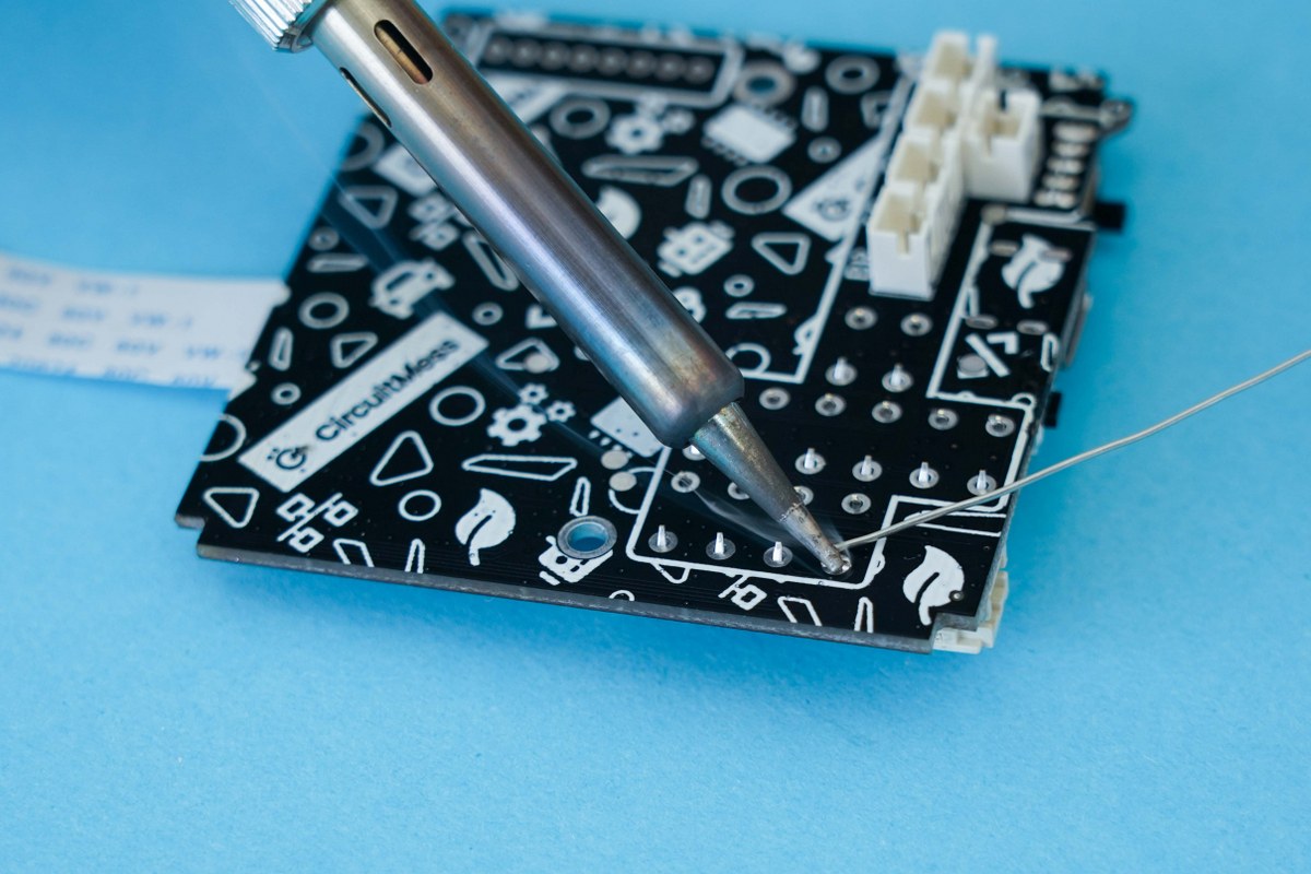
Solder the pushbuttons
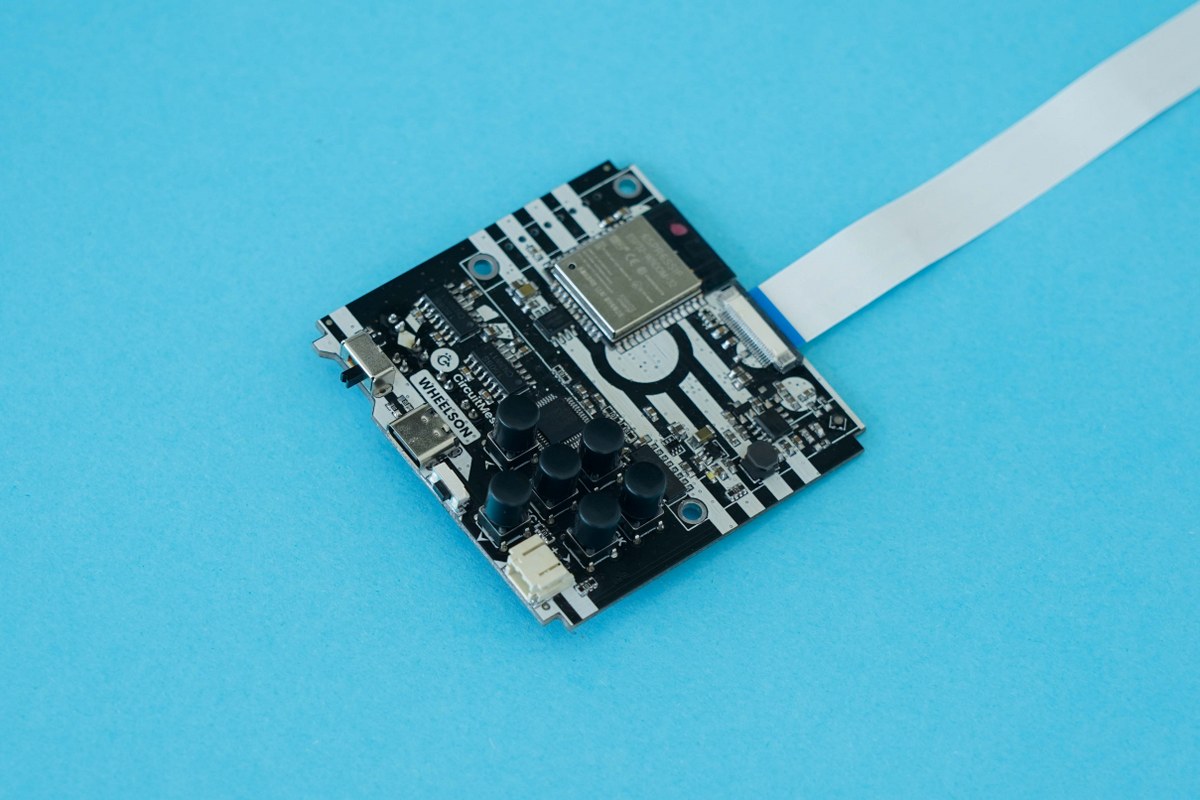
Pushbuttons soldered to the board
Part three - Putting on the button caps
So, we included some more comfortable button caps that will solve this issue. It's time to add them on. Here's what you need:
- The main board
- Six button caps
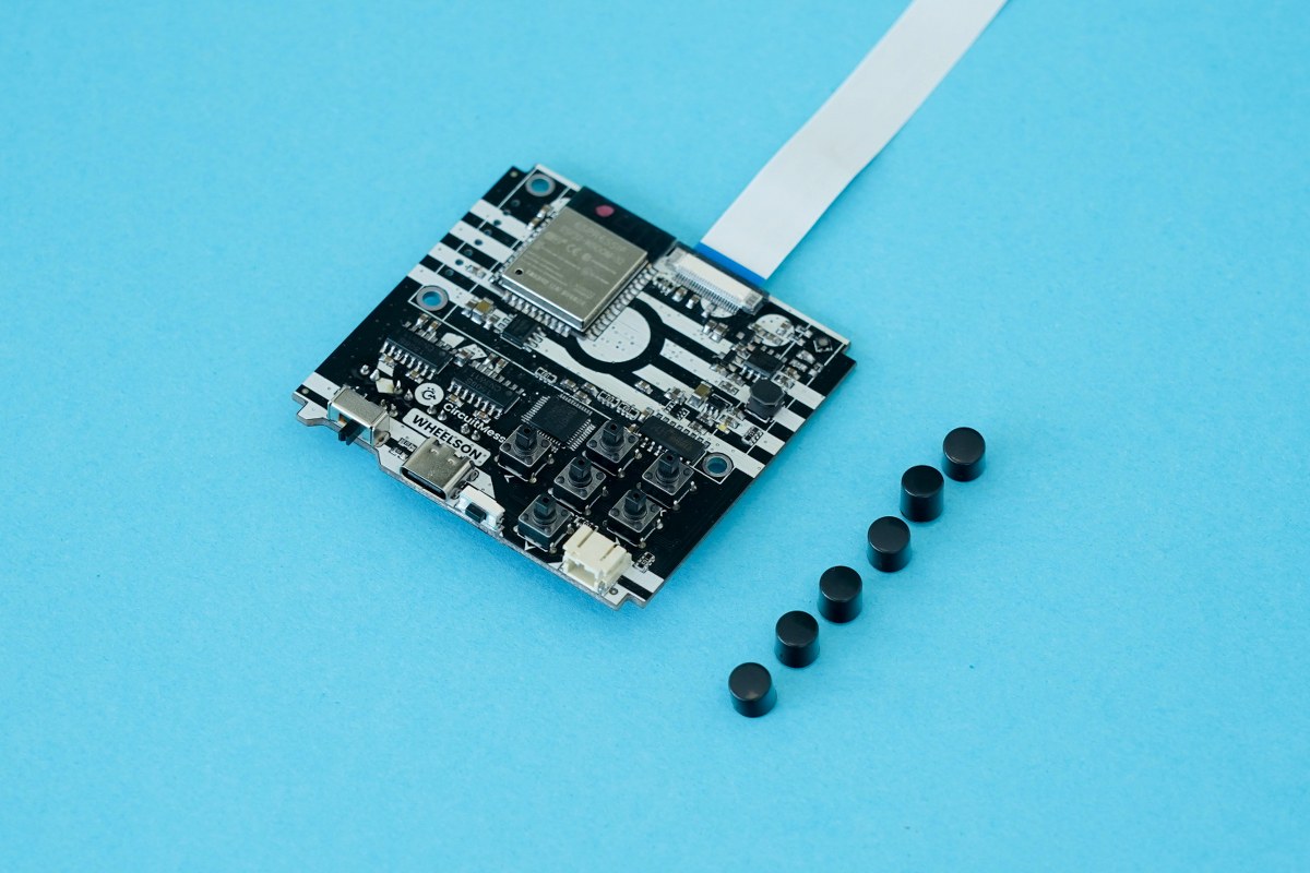
The main board and six button caps
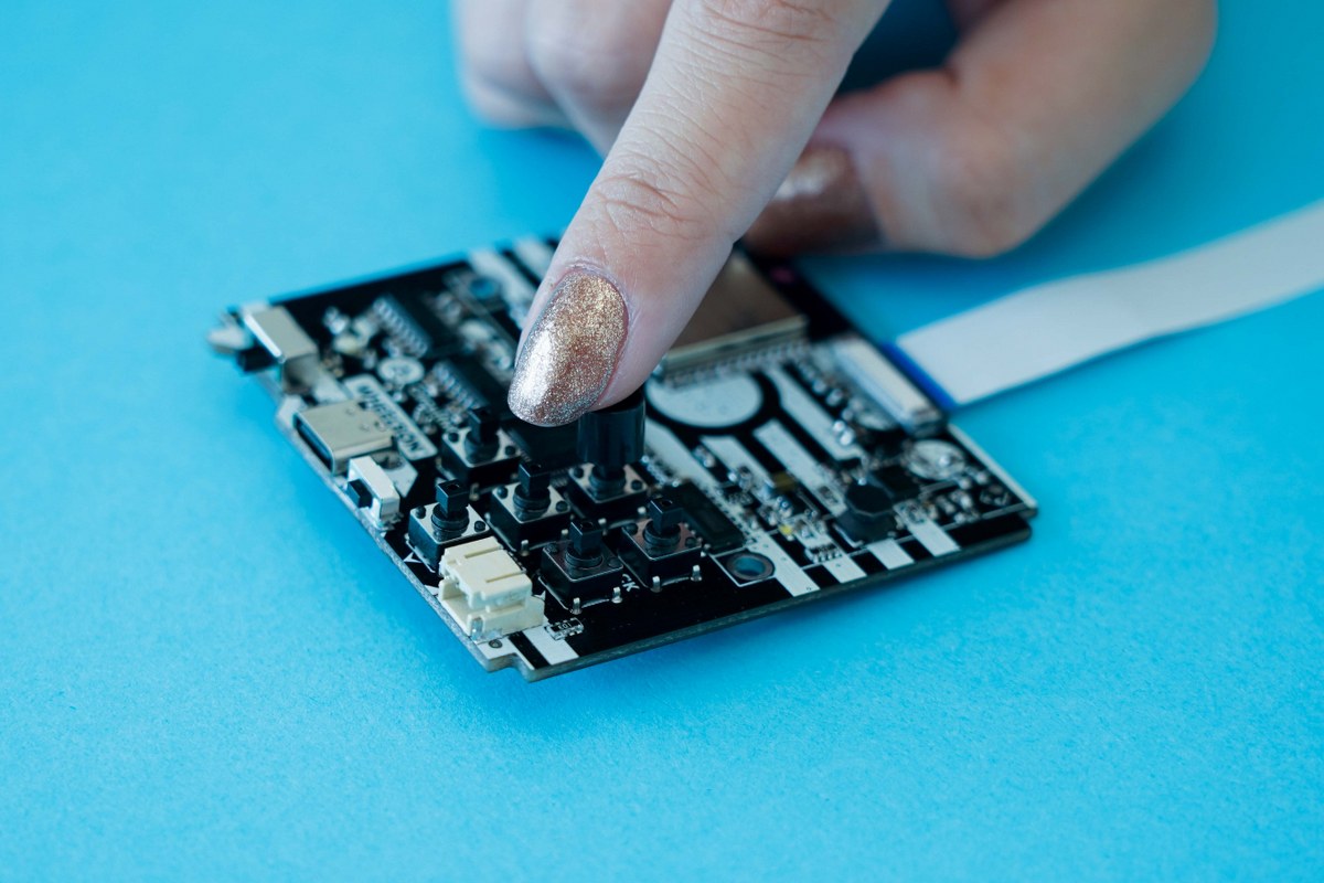
Push the button cap until it clicks into place
Step five - Soldering the screen
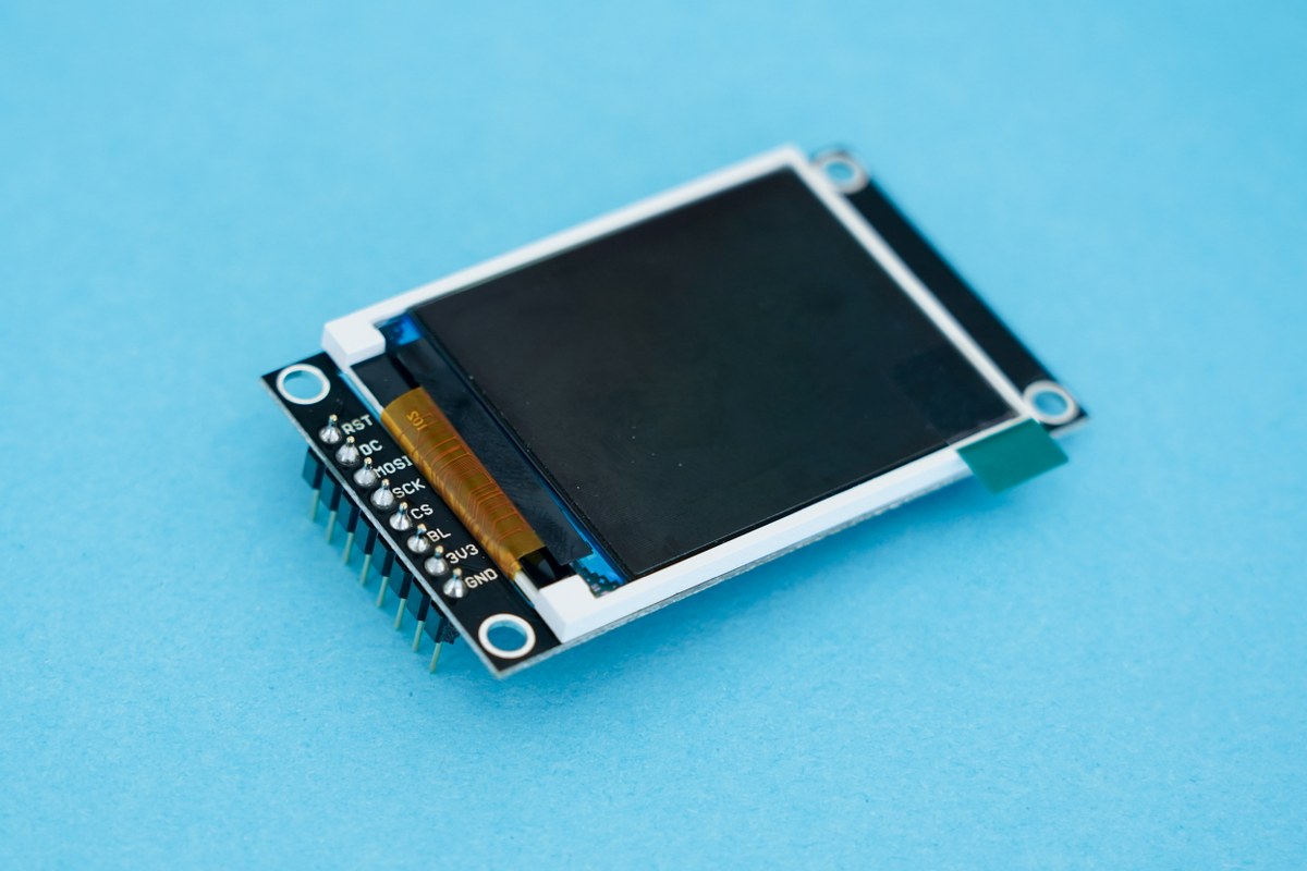
You’ll notice a little protective layer on top of the screen, which you can take off by pulling the little green tab. Don’t do that just yet though! This just ensures that the screen stays protected all the way through the soldering part.
After you’ve done your soldering, you can take it off; this will make your screen really shine. Everything will work just as well, even if the protector remains on, so don’t worry too much about it. Let's just jump right in!
You'll need the following parts to begin with:
- The screen
- The header pins.
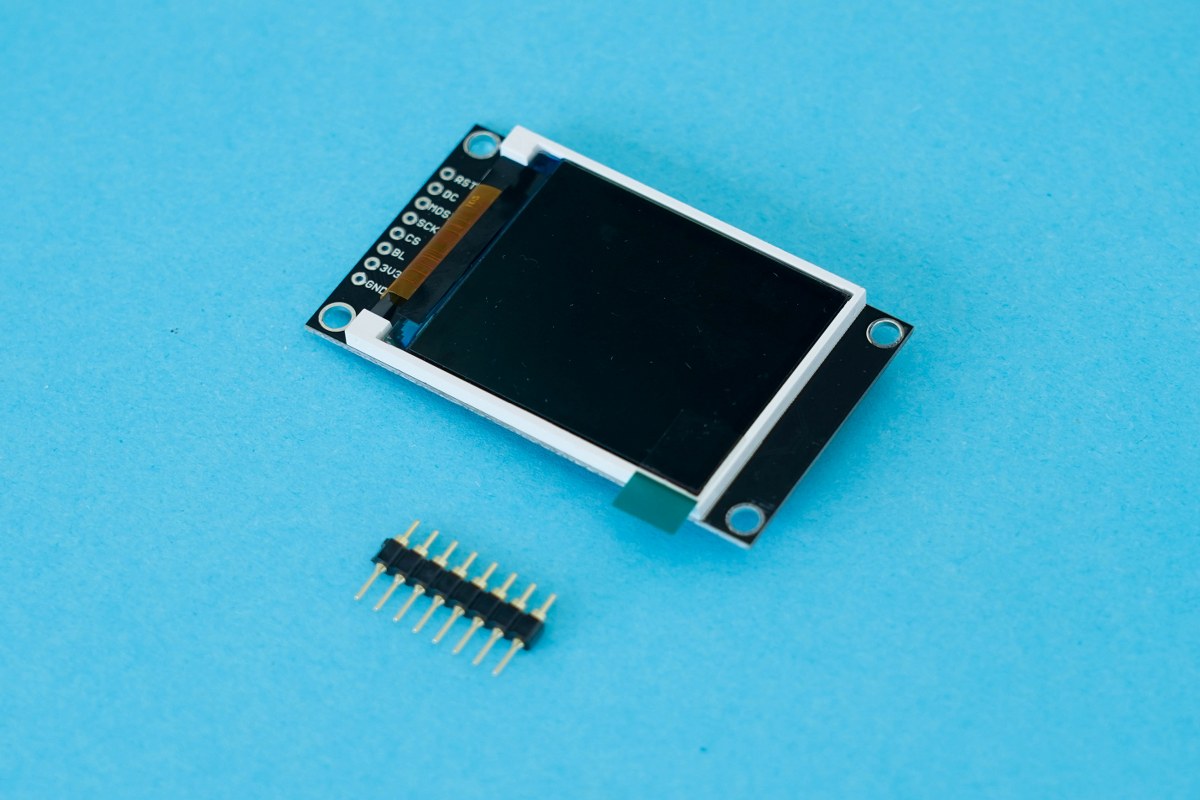
Insert the pins into the board with the screen.
Be careful when inserting the header pins since the top and bottom parts are slightly different. The part you want to insert into the screen is the shorter side (in the picture above, it will be the top part of the header pins).
It's soldering time! Now, bear with us, this is important.
Pins should be soldered perpendicular to the screen. There is a useful tip that you can use for this, so keep reading.
1) Solder just the first pin of one row of headers
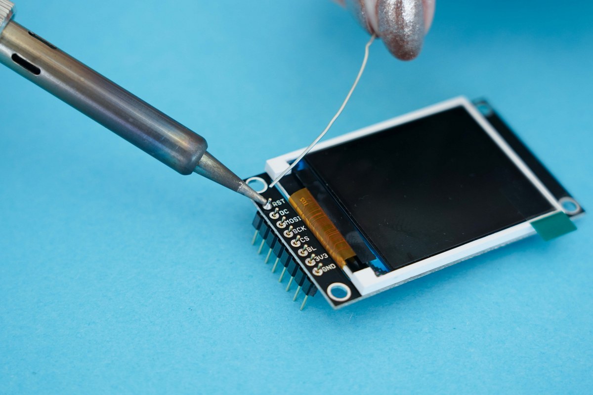
Solder the first pin
2) When the first pin is soldered, check if the header pin is perpendicular to the board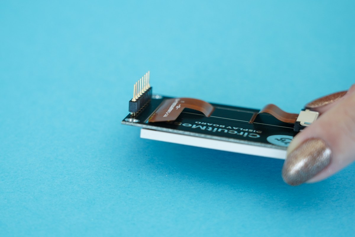
(Watch out not to burn yourself! When you are doing this, make sure you do not touch the pin that you soldered/are heating up as this will be hot!)
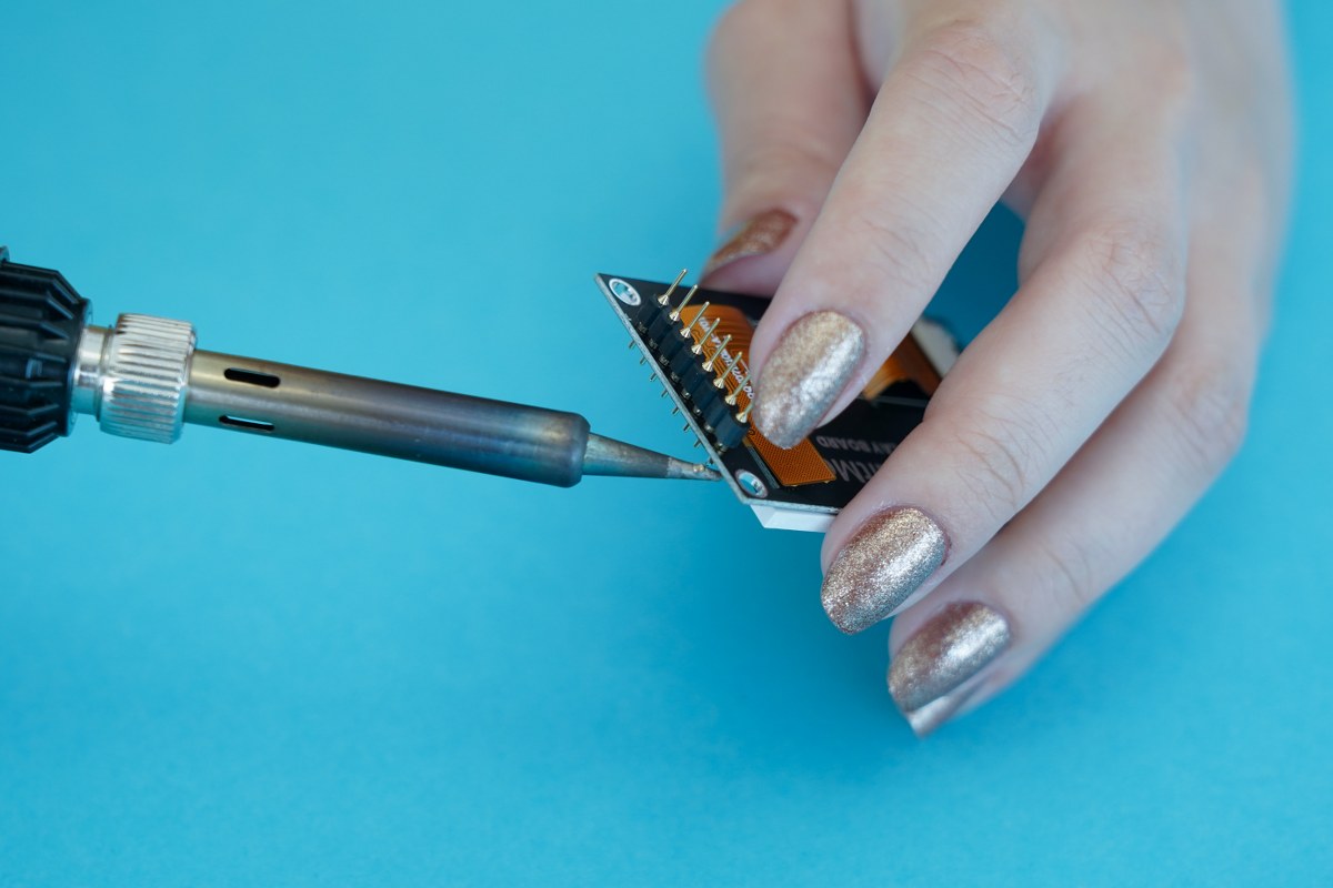
All the pins are soldered
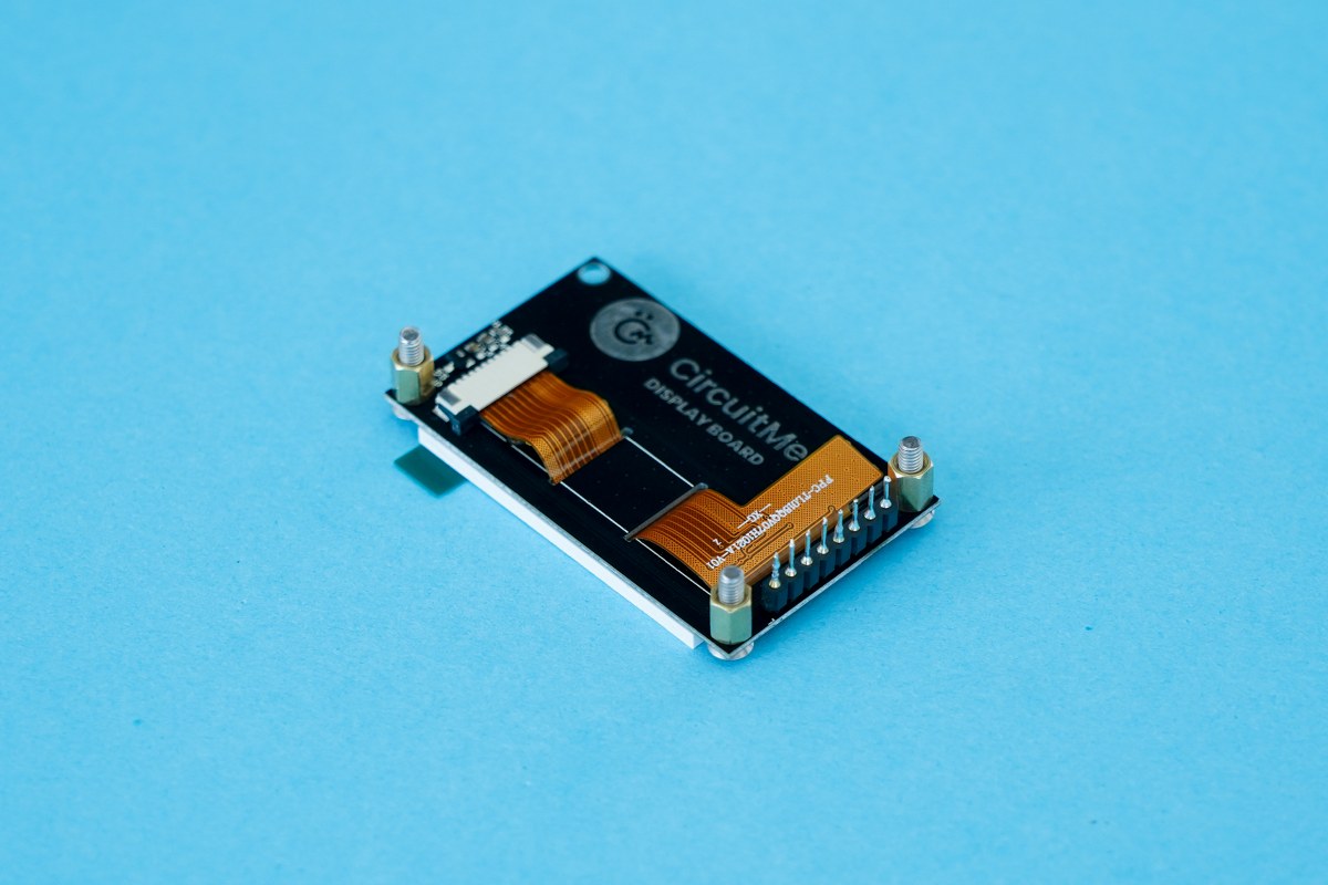
Now, we'll move on to connecting the screen to the main board. Here's what you need for this step:
- The main board
- The display board
- Three brass spacers
- Three metal nuts
- Three metal bolts
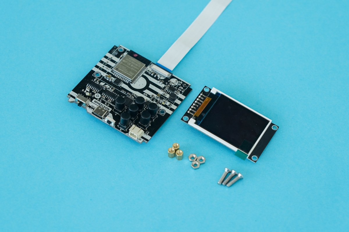
The components you need
Take one golden brass spacer and place it on the opposite side of the display board and screw the bolt in at the same time so that the spacer and bolt are secured tightly! You can do this with your hand but don't be afraid to ask for help from an adult to make sure the bolt is tightened correctly.
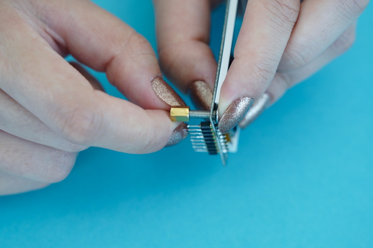
Twist on the brass spacer onto the end of the metal bolt
Tighten the bolt
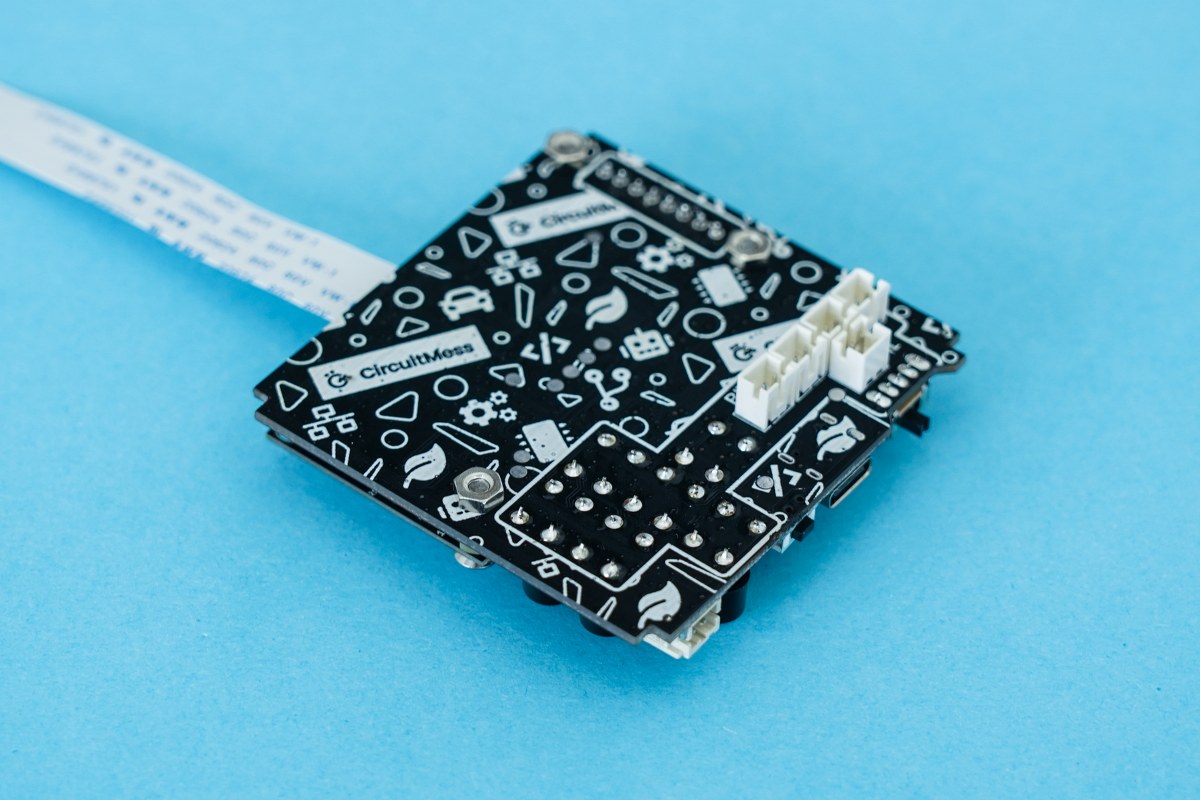
When looking at the display board from the back, the upper left corner should remain empty.
Turn the main board upside down while holding the screen so it doesn't fall out.
Take one metal nut and place it on the bottom of the bolt poking through.
Tighten it with your fingers, so it holds the screen in place.
Repeat that for all three bolts.
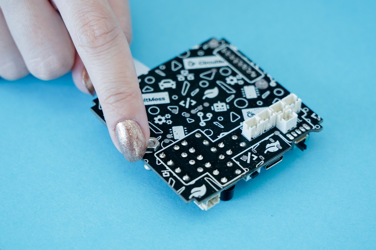
Tighten the nut so that it holds the screen in place
Repeat until all three bolts are tightened
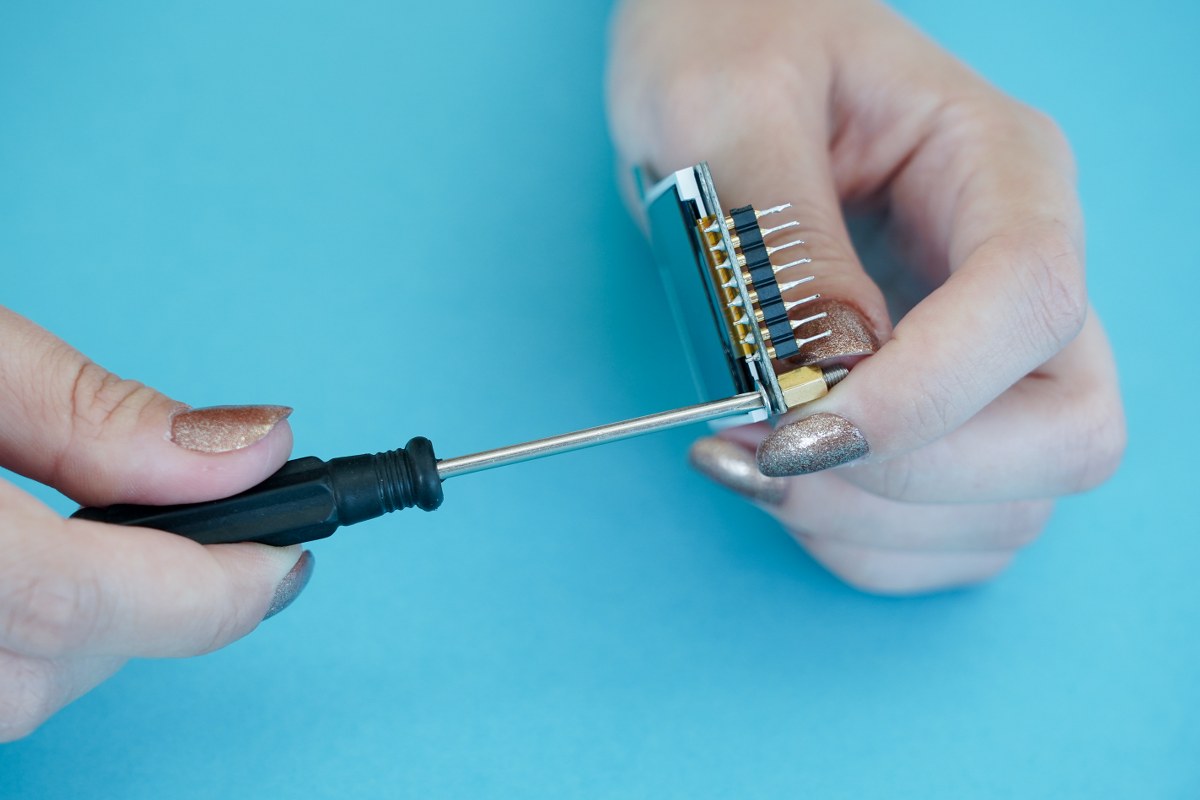
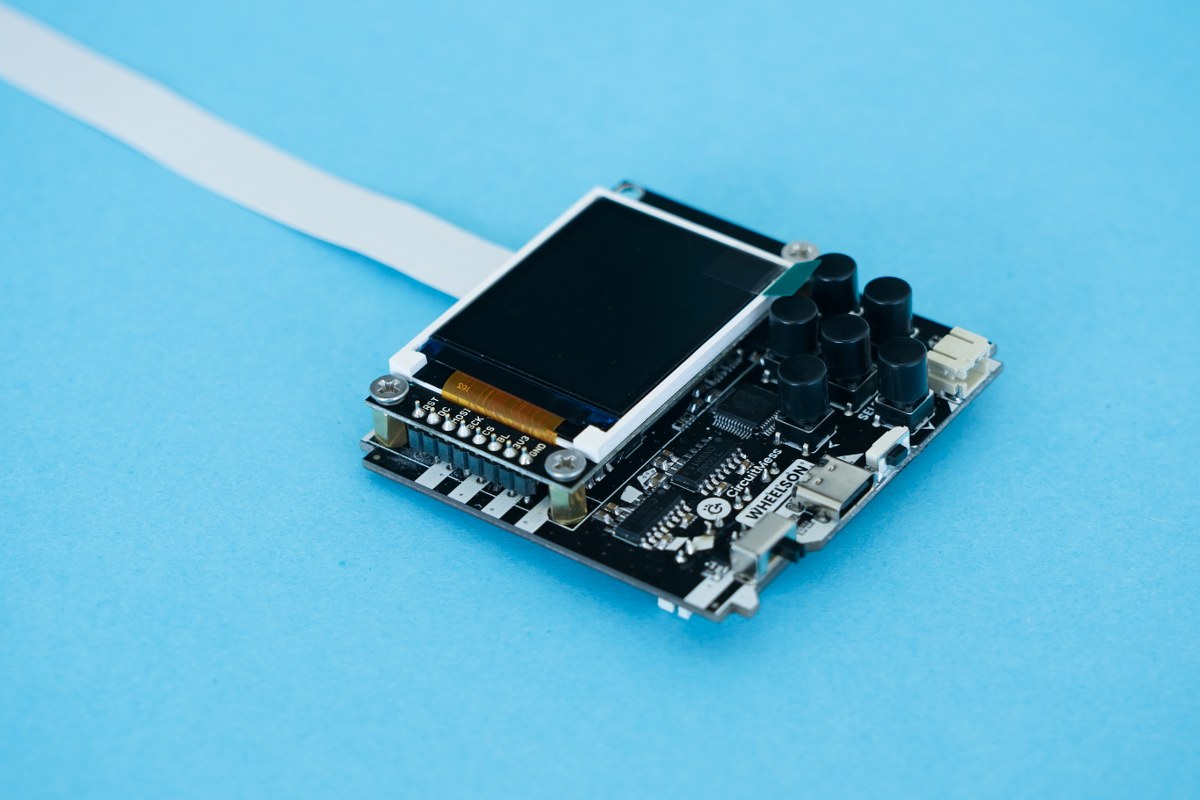
Make sure that the board is upside down, and find the pins that will connect the screen.
They're located between the two bottom spacers that you were just tightening in the previous step.
Solder the pins to connect the screen
All the pins soldered
Step six - Soldering the electromotors
When you're ready, let's move on to connecting the electromotors to the board.
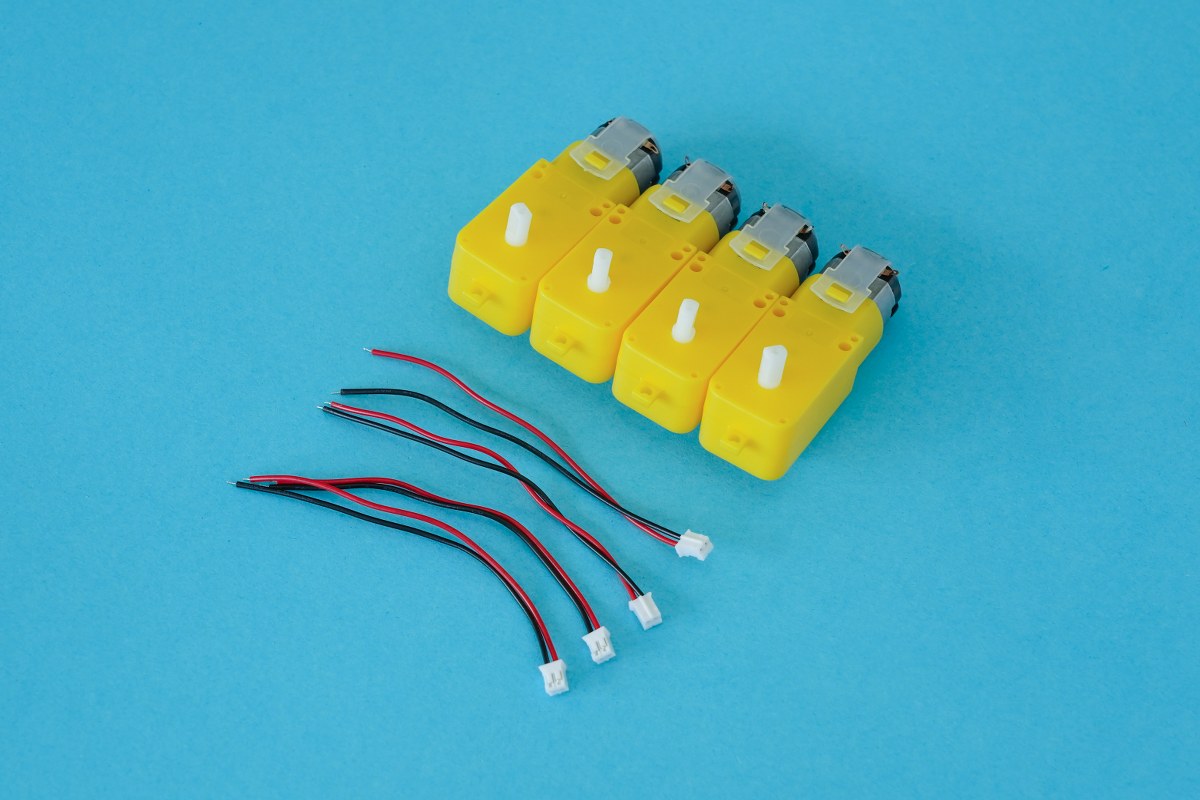
Here are the components you'll need for this:
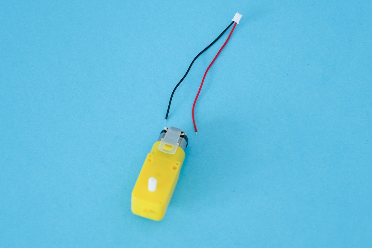
- Four electromotors
- Four JST cables
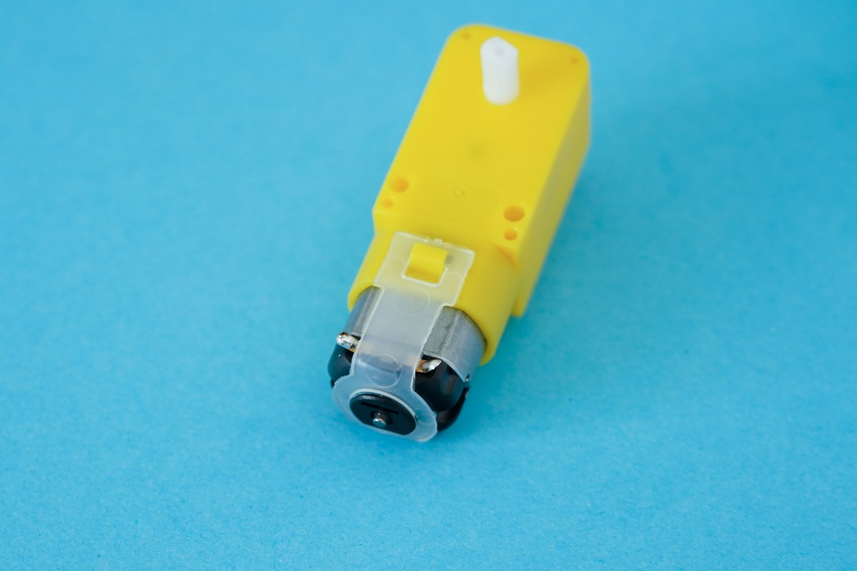
Pick up one of the electromotors. Here you'll see that each motor has two small metal pieces with a hole on the bottom. We need to put some solder in the hole to fill it in.
Use your soldering iron and some solder, and melt a generous amount of solder into the hole. Do this for all four electromotors.
Put a generous amount of solder into the hole
Holes filled with solder
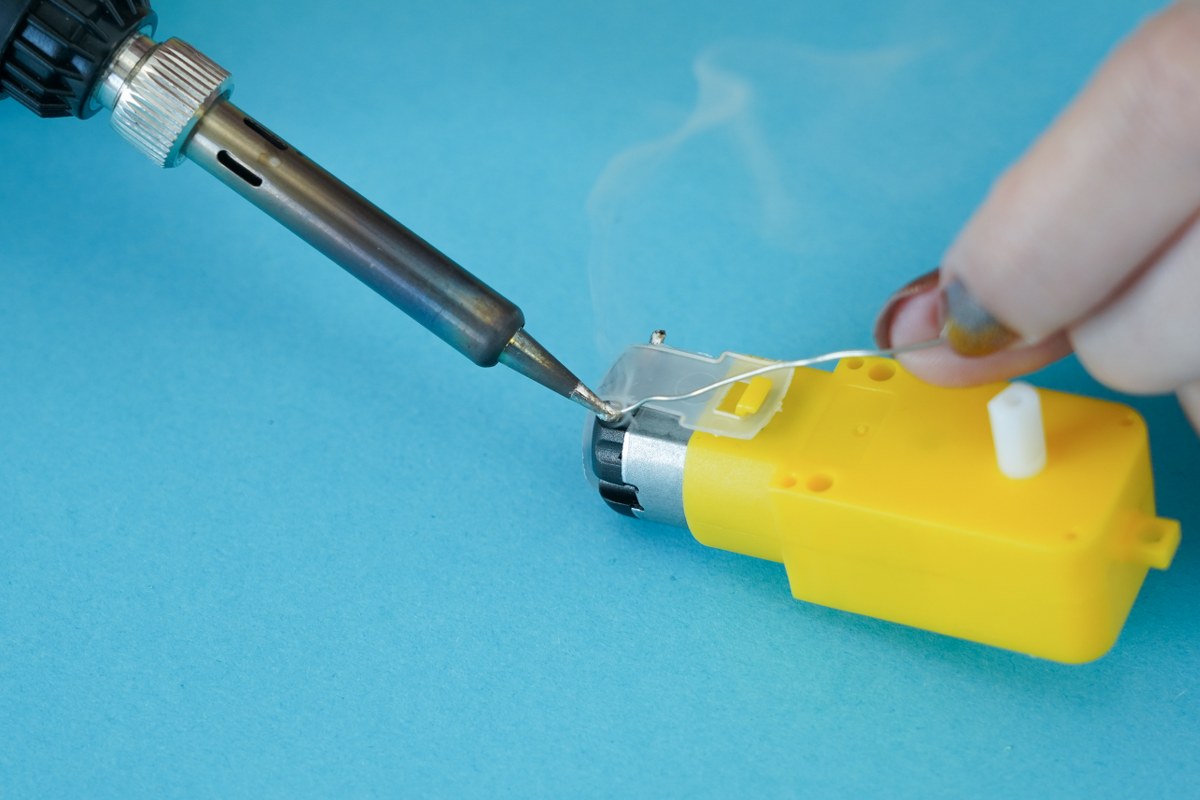
Be careful to connect the correct cable to the correct side. Here's a tip on how to do that:
- Turn the electromotor so that the white plastic tube is on the top and the metal bottom part is facing you - see the photo below.
- Solder the red wire to the left side and the black wire to the right side of the electromotor.
You'll solder these wires into the holes you just filled with solder. Using your soldering iron, melt the solder and simply stick the tip of the wire in.
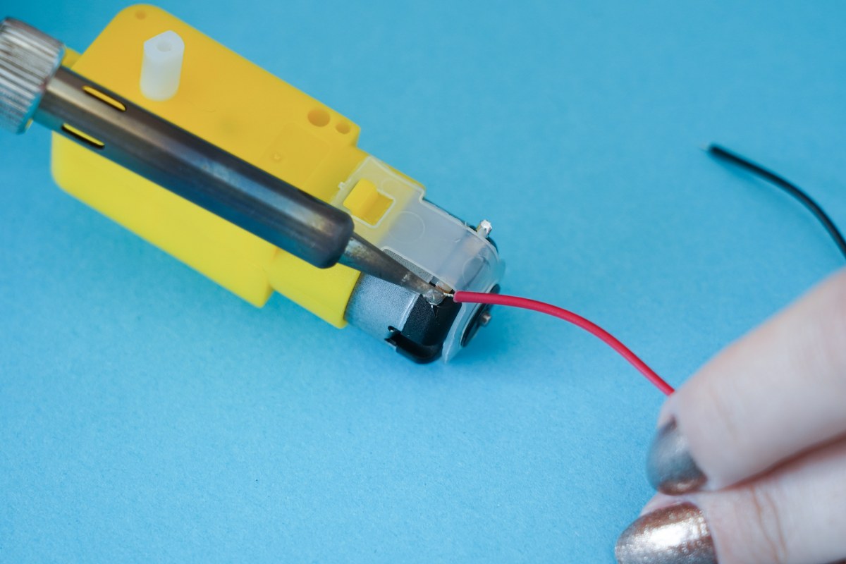
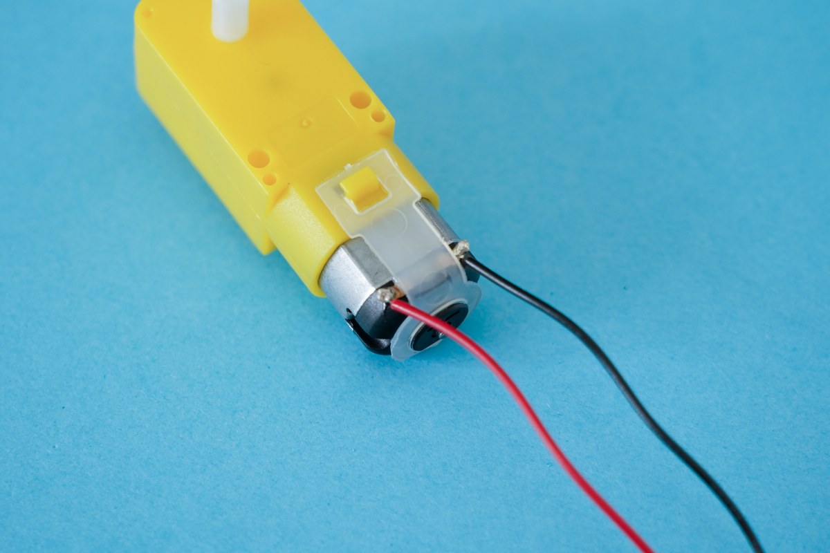
Connect the red wire to the left side of the electromotor and the black wire to the right side.
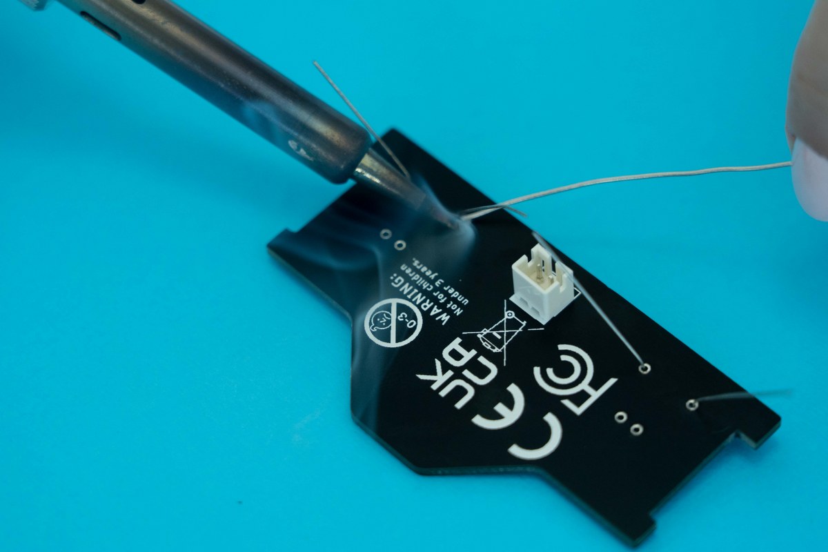
Step seven - Soldering the camera and headlights board
- Camera and headlights board
- Two resistors
- Two LEDs
- One JST connector
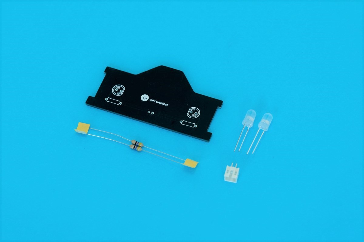
Use the photo below as a reference:
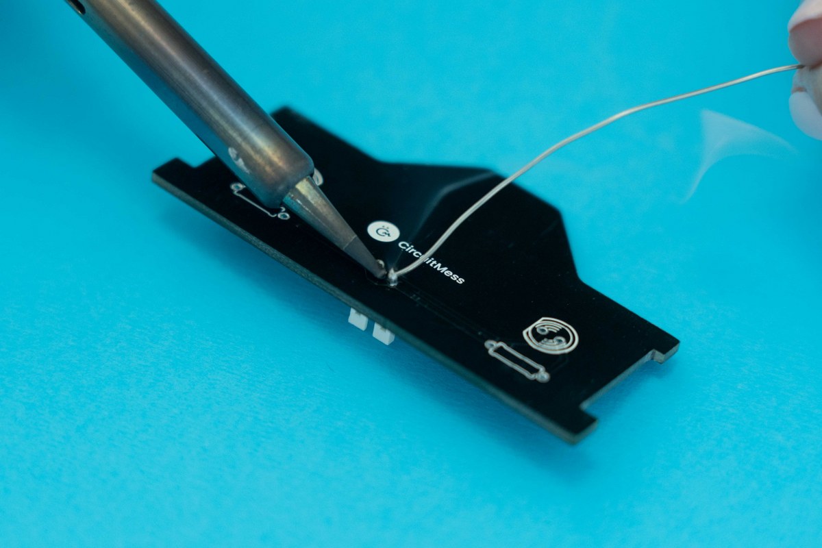
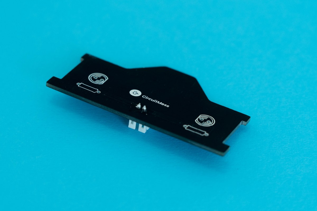
Pins soldered to the board
- Pinch the resistors with your thumb and index finger.
- Using your other hand, bend the two pins down in the same direction.
- Make sure that each side of the resistor is bent at a 90-degree angle.
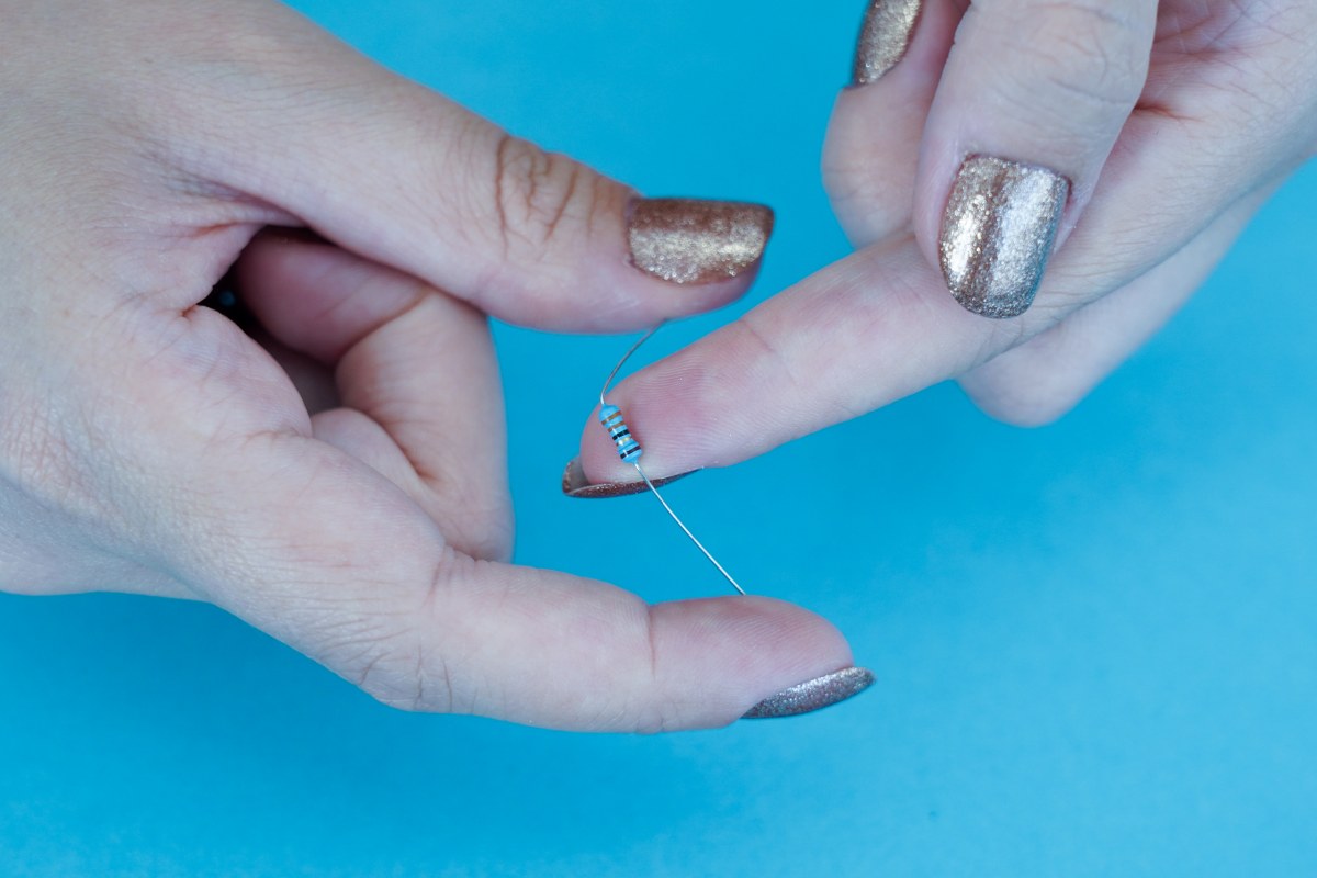
Bend the resistor
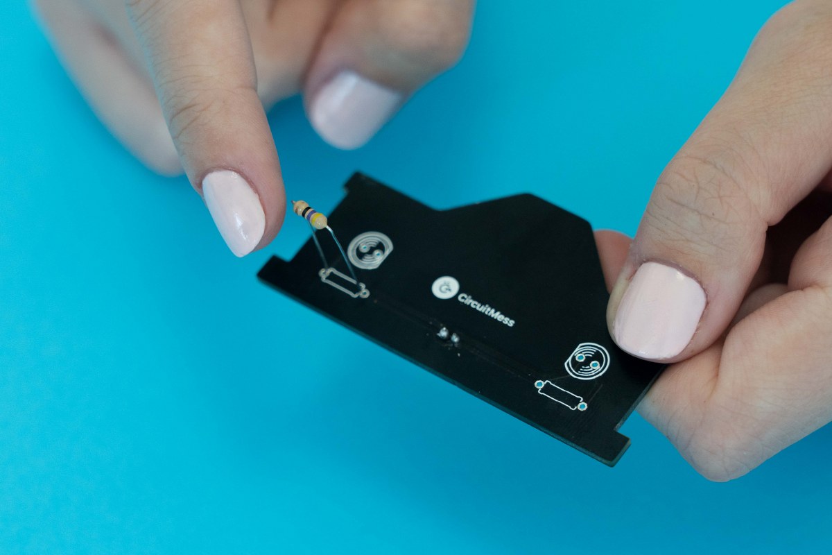
Fit the resistor to the board
Both resistors inserted through the board
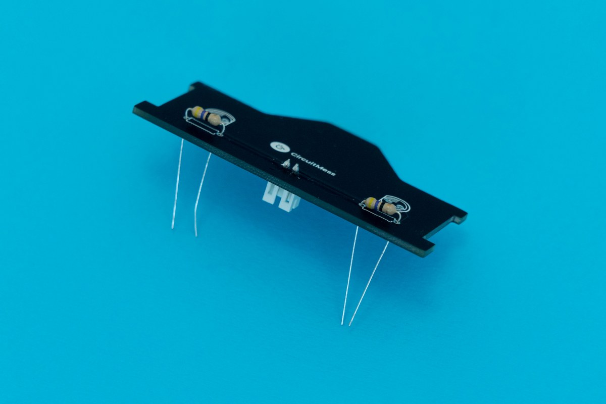
Here's a pro tip for you: bend the resistors' pins outwards, as shown below, so that they don't fall out or move around when you're soldering.
Bend the resistors' pins outwards
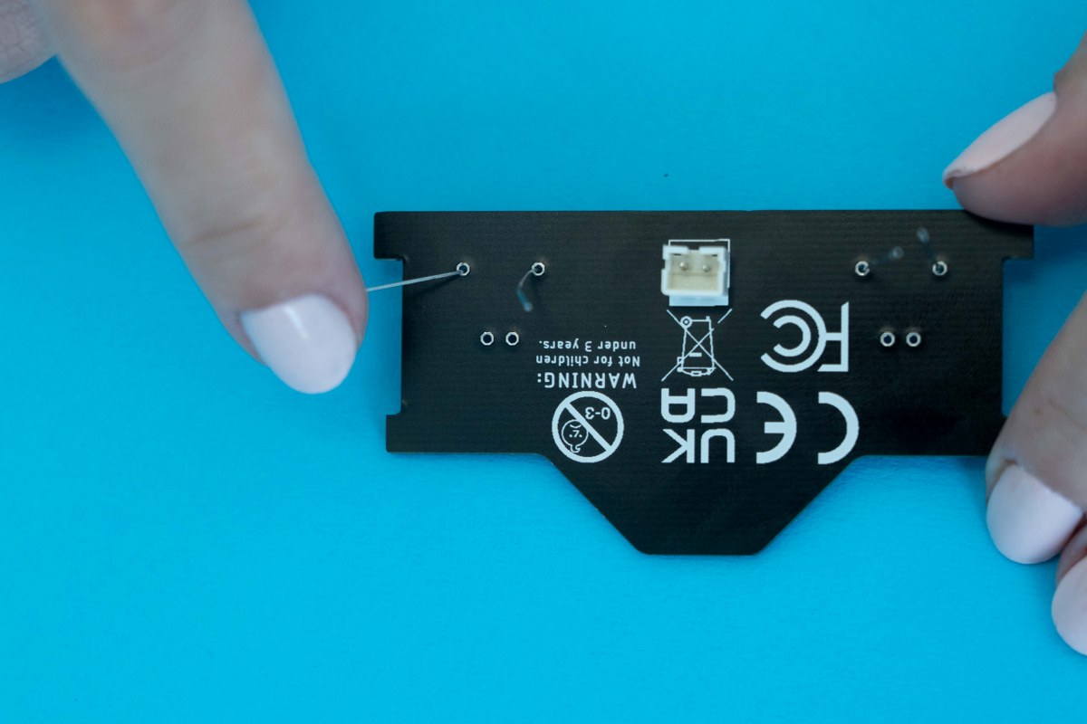
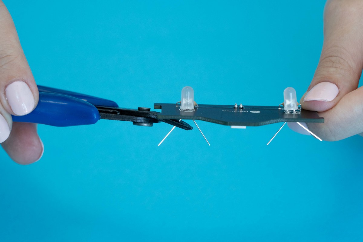
Once the resistors have been soldered to the board, it's time to cut off the excess pins. Grab your diagonal cutters and cut off the excess.
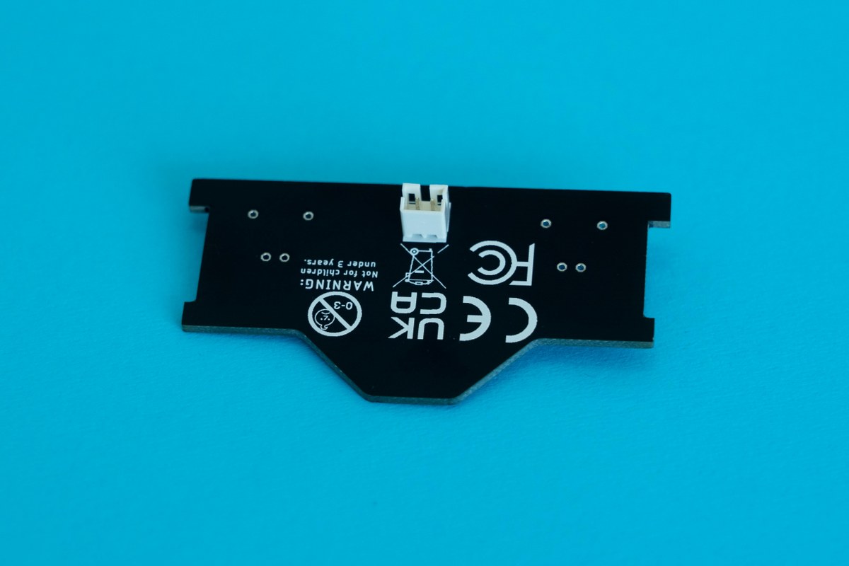
Turn the board around so that the wires are facing away from your face and eyes. Make sure that you do not scratch the PCB as this could cause some issues in the future.
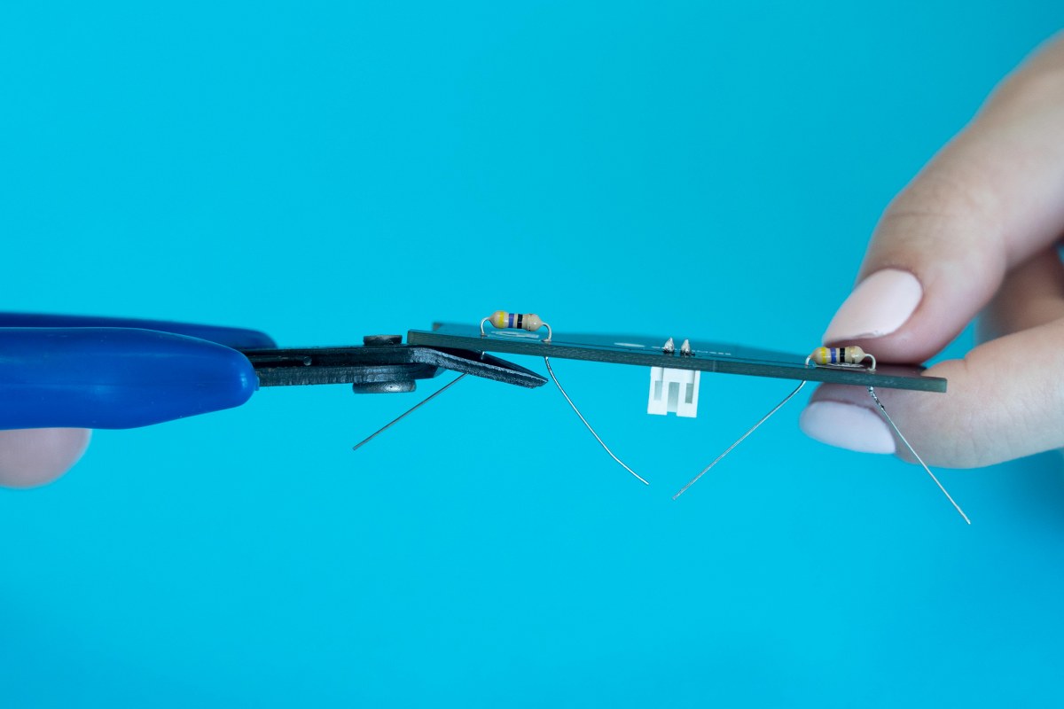
Turn the board away from your face and eyes and cut off the excess.
It's important to note how you insert the LED into the board. So take some time to inspect the LED first!.
You'll see that one of the LED's legs is shorter than the other, and if you look closely, you'll notice that one side of the LED is straight while the other is round.
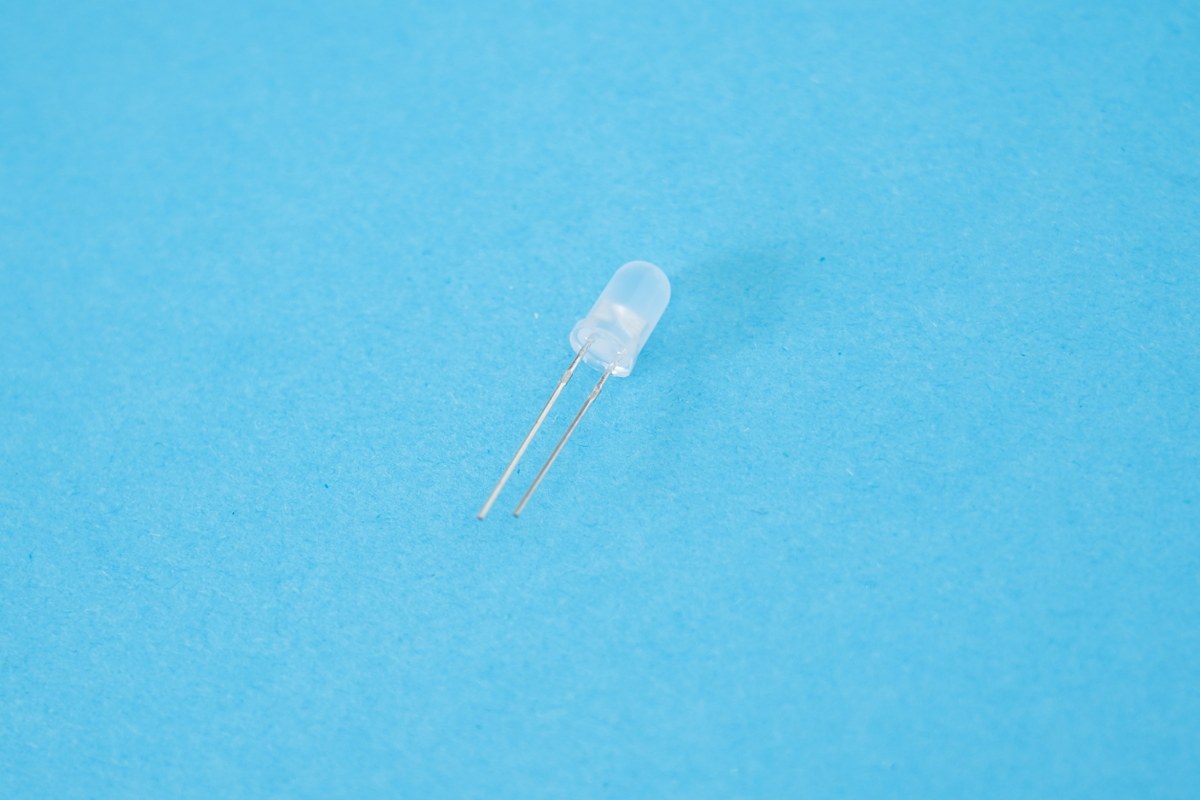
White LED
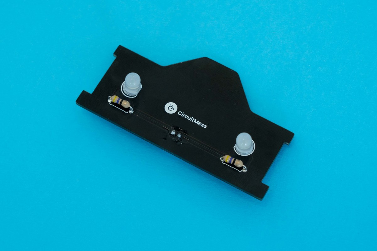
The straight edge of the LED should line up with the straight edge drawn on the board. Another reference you can use is that the LED's shorter leg should go through the hole right next to the straight edge.
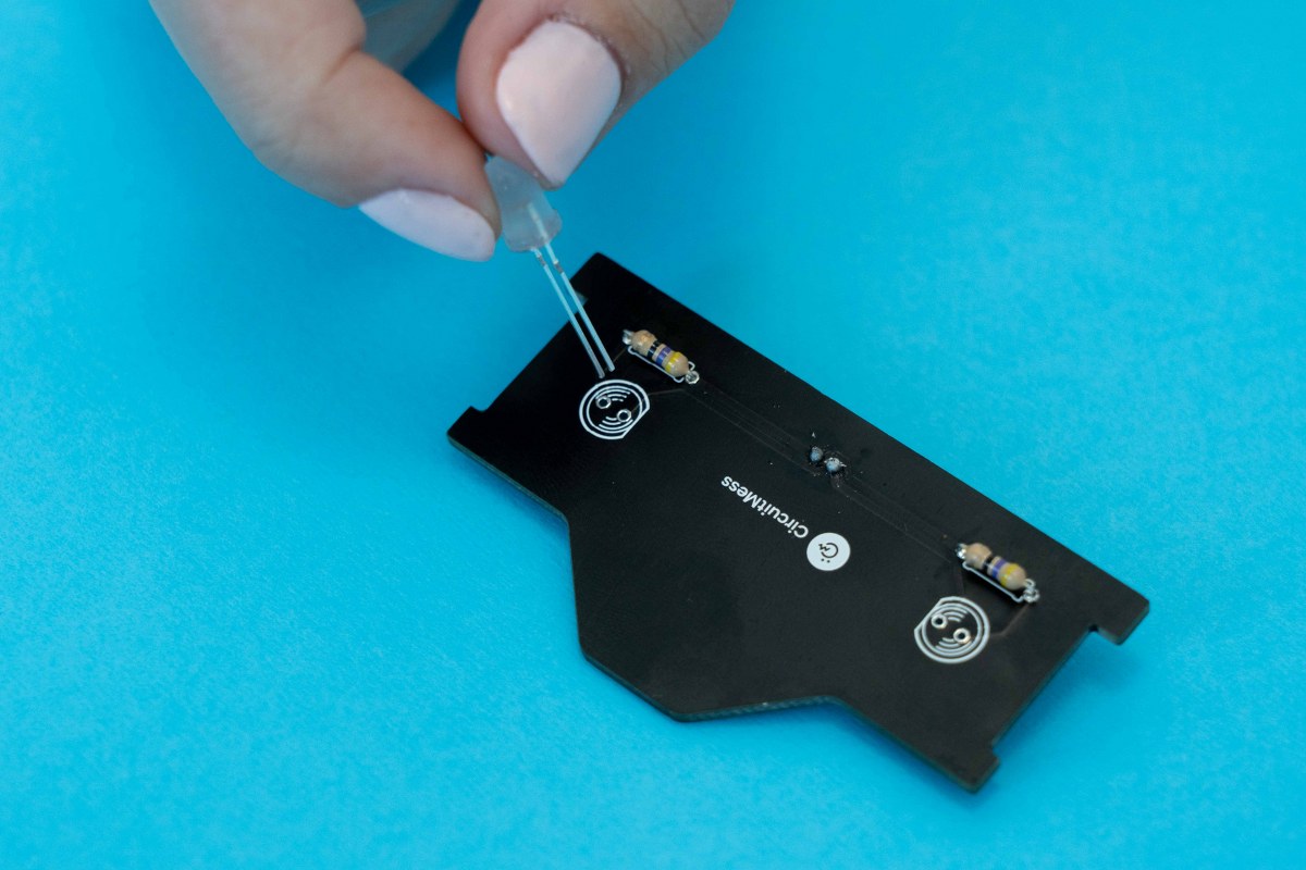
Insert the LEDs
Alright, everyone, this is the last time you're going to use your soldering iron in this project. It's time to solder the LEDs to the board!
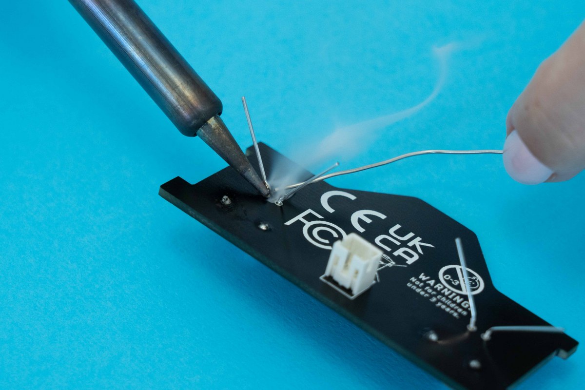
LEDs soldered to the board
Remember
We hope you had a great time soldering the components. Sadly, you'll have to turn off your soldering iron now! But we're not done yet, there are more fun steps to follow! Please turn off your soldering iron by unplugging it from the power outlet. Leave it on the soldering iron stand for at least five minutes, so it cools off before you put it away.
Ready to continue?